Model Input
While calculating the horizontal stresses for the anisotropic reservoirs using the Stress Contrast method, you need to provide additional model inputs to model the vertically transverse isotropic, VTI 3D and orthotropic reservoirs.
For the rock properties exhibiting vertically transverse isotropy (VTI), JewelSuite Geomechanics uses the transverse shear wave anisotropy derived from Stoneley wave monopole processing [1], with the assumption of flat laminations and beddings perpendicular to borehole. The cross-dipole multi-array acoustic logging tools are able to measure the shear wave anisotropy in vertical wells that are aligned with the principle stress direction. A vertically transverse anisotropic rock requires five independent elastic measurements while an orthotropic rock requires nine elastic constant measurements.
On the Model Input form, you can select between three options to characterize the horizontal stress profiles. Each options requires specific inputs on the form, in combination with the calculation method selected on the Input Definition form.
- VTI (Annie) This method simplifies the transverse isotropic model by making two assumptions, and it is referred as 'Annie' approximation introduced by Schoenberg et. al. in 1966 [2]. The approximation consists of two assumptions that are combined with three independent acoustic measurements (C11, C33, C66) to characterize the rock stiffness tensor for transverse isotropic materials. With these assumptions, the rock stiffness tensor can be described using only three independent wellbore acoustic measurements (DTC, DTS and DTSH).
- VTI 3D (XDipole) With this method, the azimuthal anisotropy obtained from X-Dipole processing [3] (DTSF and DTSS) are used as input along with the acoustic slownesses (DTC and DTS) and transverse shear anisotropy (DTSH). In addition, you need to provide the vertical to horizontal Biot coeffiecient (ZETAV), and the Thomsen Coefficient (Epsilon and Delta) which is used to calculate the stiffness tensor C11.
- Orthotropic The orthotropic rock model calculates the horizontal stress profiles using the Biot's anisotropy coefficients and the compressional and shear wave velocities. You also have the option to provide the elastic moduli (Young's modulus, Poisson's ratio and Shear Modulus), instead of calculating the stiffness tensors based on the acoustic data. There are options to choose from the drop down menu when working with Orthotropic rock models:
- Velocities With this option, the dynamic stiffness tensors are calculated using nine ultrasonic velocity measurements. These measurements include three compressional velocities in the three principle directions along with three oblique compression wave velocities at an angle of 45 degrees (see figure below), and three shear wave velocities (two vertical polarized to 'X' and 'Y' directions plus the horizontal shear). When this option is selected, you enter these velocities as logs or constants in the table below on the form.
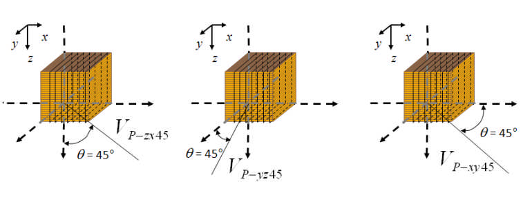
Oblique compression wave velocity measurements at 45 degree angles on each plane used to characterize non-diagonal term of the orthotropic stiffness tensor. click to enlarge
- Estimated velocities With this option, the velocities are computed using the acoustic log data, that is used in the VTI model, along with the Thomsen Coefficient and Biot's anisotropy coefficients. The oblique velocities at 45 degrees are calculated using the pro-rata coefficient 'Ratio Vel'.
- Moduli With this option, you first calculate the compliance tensor using the Young's modulus, Poisson's ratio and Shear Modulus values. The compliance tensor in then inverted to generate the stiffness tensor and consequently the horizontal stress profiles are generated. Enter the values of the moduli in the table below on the form as logs or as constant values. Enter the Young's modulus values in the principle directions, while the Poisson's ratio and Shear modulus are provided in the planar directions ZX, ZY and YX.
- Velocities With this option, the dynamic stiffness tensors are calculated using nine ultrasonic velocity measurements. These measurements include three compressional velocities in the three principle directions along with three oblique compression wave velocities at an angle of 45 degrees (see figure below), and three shear wave velocities (two vertical polarized to 'X' and 'Y' directions plus the horizontal shear). When this option is selected, you enter these velocities as logs or constants in the table below on the form.
Providing model inputs for vertically transverse isotropic (VTI) and orthotropic models
At the top of the form, select the method or a combination of methods that you want apply to your anisotropic model. Check the adjacent checkboxes to select either VTI (Annie), VTI 3D (XDipole) or Orthotropic. For the orthotropic option, select an input option from the drop down that will be used to calculate the horizontal stress profiles.
Biot's Anisotropy Coefficients
ZETAV Vertical to horizontal anisotropic Biot coefficient. Select a log from the drop down list or enter a constant value between 0 and 1.
ZETAH Horizontal to horizontal anisotropic Biot coefficient. Select a log from the drop down list or enter a constant value between 0 and 1. Not applicable for VTI (Annie) method.
Acoustic Data
DTC Vertical compressional slowness. Select a log from the drop down list.
DTS Vertical shear slowness. Select a log from the drop down list.
DTSH Horizontal shear slowness. Select a log from the drop down list.
DTSS Slow vertical shear slowness. Select a log from the drop down list.
DTSF Fast vertical shear slowness. Select a log from the drop down list.
Thomsen Coefficient
Epsilon Coefficient for the 3D model C11 calculation. There are two options to select from the drop down list: <Epsilon equal to Gamma> or <Gamma correlation>
Delta Coefficient for the 3D model C11 calculation. Select a log from the drop down list or enter a constant value.
Density Data
Select a Density log from the drop down list.
Velocity Data
RatioVel Pro-rata coefficient to compute oblique velocities at 45 degrees. Active only when working with an orthotropic model using estimated velocities. Select a log from the drop down list or enter a constant value.
External Stresses
The fields in this section are active only if:
- You have selected 'External Stress' or 'External Stress Gradient' as calculation method on the Input Definition form.
- You have entered stress calibration data instead of strain data.
Shmin Tectonic Stress Tectonic stress in the direction of minimum horizontal stress. Select a log from the drop down list or enter a constant value.
SHmax Tectonic Anisotropy Tectonic horizontal stress anisotropy. Select a log from the drop down list or enter a constant value.
Shmin Tectonic Stress Gradient Tectonic stress gradient the direction of minimum horizontal stress. Select a log from the drop down list or enter a constant value.
Velocities and Moduli
This table is active only when working with an orthotropic model with velocities or moduli as input. There are five tabs to enter the inputs, of which the first two tabs are applicable when working with velocities while the last three tabs are active when you want to enter the rock moduli.
Compressional Velocity Enter the compressional velocities in the three principle directions (X, Y and Z) and the oblique velocities at 45 degrees (ZX, ZY, YX). For each velocity, either select a log or enter constant value by activating with the checkbox.
Shear Velocity Enter the shear wave velocities in the three planar directions (ZX, ZY and YX). For each velocity, either select a log or enter constant value by activating with the checkbox.
Young's Modulus Enter the Young's modulus in the three directions (X, Y and Z), either by selecting a log for each direction or by entering a constant value by activating with the checkbox.
Poisson's Ratio Enter the Poisson's ratio in the three planar directions (ZX, ZY and YX), either by selecting a log for each direction or by entering a constant value by activating with the checkbox.
Shear Modulus Enter the Shear modulus in the three planar directions (ZX, ZY and YX), either by selecting a log for each direction or by entering a constant value by activating with the checkbox.
Once you have provided all the model inputs for the anisotropic model, you can proceed to the Model Output form where you can select the output logs and (re)calculate the horizontal stress profiles.
References
- Tang, X.M. 2003. Determining formation shear-wave transverse isotropy from borehole Stoneley-wave measurements. Geophysics. 68: 118–126.
- Schoenberg, M., F. Muir, and C. M. Sayers. 1996. Introducing ANNIE: A simple three parameter anisotropy velocity model for shales. Journal of Seismic Exploration. 5: 35–49.
- Tang, X.M. and R.K. Chunduru. 1999. Simultaneous inversion of formation shear-wave anisotropy parameters from cross-dipole array acoustic waveform data. Geophysics. 64: 1502–1511.