Using the Zonation Model view
Formation pore pressure is explicitly calculated only in high-gamma lithologies, which are typically shales. To determine the lithology from the selected gamma-ray log, a default discriminator is used, with the boundary between high and low gamma-ray counts indicated by a red vertical line in the Zonation Model track. By default, high gamma-ray counts indicate shale, and low gamma-ray counts indicate sandstone. The unlabeled lithology track is filled in to the right of the Zonation Model track with symbols to indicate the sand and shale lithologies.
On either side of the red discriminator line are two data value indicators: a blue line to the left indicates 25% of the maximum data values, while a green line to the right indicates 75% of the maximum data values. In some cases, a dotted blue or green line may be observed in the Zonation Model, this dotted line indicates a gamma ray value that is outside of the observed track. These are used to determine 0% and 100% shale volume, respectively.
The default discriminator and the 0% and 100% shale volume bounds are determined independently within the different zones of the well. The zone boundaries are introduced automatically at any user-defined marker, and at any casing or hole-diameter change specified in the Well Schematic tabbed page of the Well Information window.
You may modify the default values of all three bounds within any of the defined zones. To alter the default value of the shale discriminator in any zone, click and drag the red vertical line to the desired cut-off value. You may also alter the blue 0%-shale line and green 100%-shale boundaries in the same way. You can set these discriminators to specific values on the Zonation/Segment Settings form as well. The Zonation/Segment Settings form is detailed later in this section.
Defining a new zonation segment
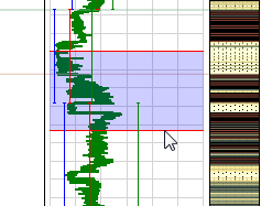
Manual zone creation in the Zonation Model view click to enlarge
You can create a new zonation segment when you select a 'Manual' calculation type on the Lithology Model form. To create a new segment you need to select the Manual option, then click and drag a selection box (in the same manner in which you drag a selection box while compositing logs) in the Zonation Model track at the depth you want the new segment created.
Once you are satisfied with the selected depth range, double-click anywhere within the segment to create a new zonation segment. A prompt appears, asking you to confirm that the existing zonation is overwritten with the new selection. In the Zonation/Segment Settings view you can find the new segment labeled as “Zonation”. Note that the Start and Stop MD and TVD of the affected zonations are automatically adjusted upon creation of the new segment.
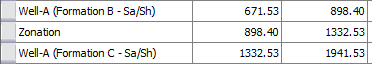
The newly created zone in the Zonation/Segment Settings view. Here you can see the top and bottom bounding depths of the zone. click to enlarge
Creating a new segment in the Zonation/Segment Settings view
When the calculation type on the Lithology Model form is set to Manual, you can create new zonation segments on the Zonation Model form. First, determine the depth range at which you want the new segment and then right-click on the segment that resides above or below this new segment. For example, in the image below showing a number of existing segments, if you want a new segment at the bottom of Formation C (1941.53 MD), you right-click the Formation C row and select Insert zonation below.
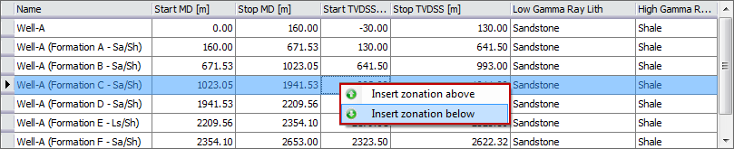
Creating a new zonation in the Zonation/Segment Settings view using the right-click menu in the table click to enlarge
This action adds a new segment, “Zonation”, and enables you to define the Start and Stop MD values. After you define these values, you are asked if you want to overwrite the existing zonations. Clicking OK recalculates the zonations and fills in the Start and Stop TVD and the Low Gamma and High Gamma lithology values.
Swapping Zonation tracks in the Well View
The application supports the creation of multiple cases for the same wellbore, allowing you to create different interpretations of your data. If your solution includes multiple cases associated with the same wellbore, you can display the Zonation tracks from the different cases using the context menu in the Well View. This provides a quick and easy method of analyzing the different zonation models in your solution.
- In the Zonation Model view, or any Well View with a Zonation track, right-click in the Zonation track and hover over Source 1D Case. A list of the other cases associated with the same wellbore appears.
- From the list, select the case containing the Zonation Model that you want to display.