Around The Hole
When you work with the Around The Hole form, you can study compressive failure only. You can include isotropic and anisotropic strength models, as well as temperature effects. Although there is no option to study tensile failure using the Around The Hole form, the flexible plotting capabilities provided in the link to view allow the display of all of the stress components and stress trajectories, which can be used to study the likelihood of tensile failure surrounding the well.
Specify Bedding Planes
The options under Specify Bedding Planes are only enabled if you have checked the Bedding Planes option on the Advanced Mode form.
One plane of weakness - Use this option to predict shear failure of discrete bedding or fracture planes close to the well. Apart from the selections you have made on the Model Definition form, the input for the calculations is taken from the Bedding Planes tab on the Advanced Mode form. The approach used is to model the strength of the intact rock and that of the weakness planes independently. It is straightforward to extend this model to study the likelihood of slip along fractures or bedding planes intersecting the well.
When evaluating slip on a single fracture set, a further extension is to consider the effect of changing the pressure of fluid inside the fracture. If the fracture is in communication with the well, then the pressure could take any value between the original pore pressure and the pressure of the drilling mud. For an overbalanced well, this analysis is useful to evaluate the benefit of fluid loss additives as an alternative to changing the mud weight in a fractured rock or fault zone. The values for the parameters that are used for the calculations, Bedding Dip, Bedding Dip Azimuth, Bedding Cohesion and Sliding Friction Coefficient are taken from the Advanced Mode form.
Orthotropic strength - Use this option to evaluate failure when the material properties of the rock that is being drilled differ in perpendicular directions. Failure of material with orthotropic rock strength is similar to failure of anisotropic material, and is controlled by the isotropic strength parameters as well as the amount of anisotropy determined by the values of A and B. When you have selected this option, you have to define the A and B parameters. You do this on the Orthotropic Strength form that is opened via the icon ![]() or via Bedding Planes > Orthotropic Strength.
or via Bedding Planes > Orthotropic Strength.
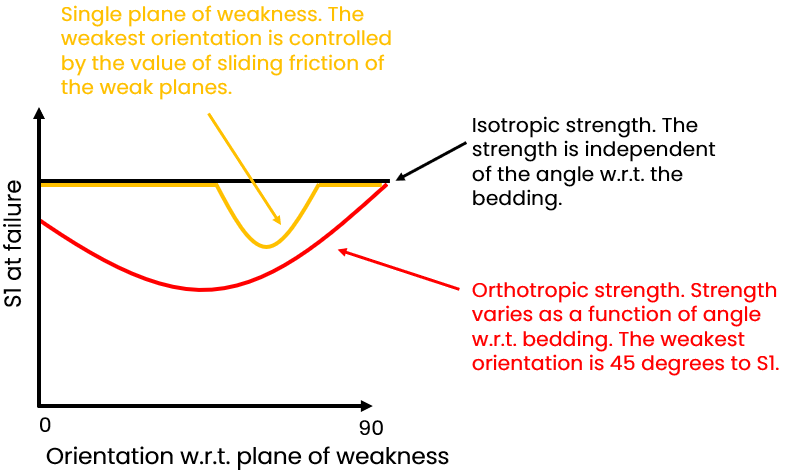
Schematic example of strength (expressed as the maximum stress S1 at failure of the sample) as a function of angle with respect to the weakness planes for both options. One plane of weakness is drawn in orange, orthotropic strength in red click to enlarge
Multiple planes of weakness - Use this option to analyze the effects of multiple planes of weakness, such as occur in fault zones, in highly fractured shales, in rubble zones adjacent to mobile salt bodies, or in coal. In thinly bedded shales, deformation often results in the creation of multiple sets of fractures perpendicular to bedding. In coals, cleats that typically form perpendicular to bedding include face cleats (continuous fractures) and butt cleats (discontinuous fractures that connect adjacent face cleats). In these formations, failure of only a single set of weak planes may not be problematic, however when more than one set fails it may be catastrophic.
Selecting this option, it is possible to superimpose the results of running several different plane-of-weakness models in a single analysis. You can determine the relative risk of instability in terms of the number of fracture sets that are likely to slip given the current stress state, the wellbore orientation, and the mud weight. The risk is weighted either by fracture density or by the number of fractures intersecting the well per unit well length. For this reason the spacing is normalized by the hole diameter.
You specify all the information that is needed on the Multiple Planes of Weakness form that is opened via the icon ![]() or via Bedding Planes > Multiple Planes of Weakness.
or via Bedding Planes > Multiple Planes of Weakness.
Specify Temperature Effects
The options under Specify Temperature Effects are only enabled if you have checked the Temperature effects option on the Advanced Mode form. When selected, the thermally-induced stresses in the rock both at and away from the borehole are calculated, using the thermal parameters entered on the Around The Hole form.
Tau - Tau is dimensionless time at which the computations are done. Tau is calculated as follows:

where
To specify Tau, there are three options:
- Select a log from the drop-down list.
- Use a constant value.
- Calculate Tau using the values entered in the entry boxes for Borehole radius, Thermal diffusivity and Time.
Maximum normalized radius - The value you enter here determines how far off the wellbore wall the calculations must go. 1 means at the wall, 1,5 means 1,5 times the radius of the wellbore into the rock. The default value that is already filled in upon opening this form is 10.
Specify Input Data
Maximum normalized radius - The value you enter here determines the maximum radius from the hole for which results are displayed in the wellbore cross section area. The default value that is already filled in upon opening this form is 1,5.
When you have made your selections, and filled in all values that are required in the entry fields on the form, click (Re)Calculate to start the calculations. The intrinsic load-bearing capacity of the rock is calculated as a function of angle with respect to the plane of weakness. Click Show to open the dedicated Elasticity - Around the Hole View.
The lock icon on the form can have different colors and states:
|
|
Open When the lock is green and in the open position, the associated algorithm is automatically executed when a change is made to the data’s input. Current status of output data is 'up-to-date'. |
|
|
Locked, No Changes When the lock is blue and in the locked position, the associated algorithm is not updated when a change is made to the data’s input. Current status of output data is 'up-to-date'. |
|
|
Open, Red When the lock is red and in the open position, the associated algorithm is automatically executed when a change is made to the data's input. Current status of output data is 'not-up-to-date', meaning the algorithm was already executed but output data was not calculated/updated due to some errors or lack of input data. |
|
|
Locked, Red When the lock is red and in the locked position, the associated algorithm is not updated when a change is made to the data's input. Current status of output data is 'not-up-to-date'. To apply the updates, you need to click the associated (Re)Calculation button. |