Faults in a 3D grid or 3D mesh
Right-click on a fault inside a 3D grid or 3D mesh to perform various actions:
Hide (Only for context menu in a view) Hide it in your view.
Show Legend Show or hide a legend for it in your 3D View.
Display Settings
Color Pick a color to display it in the view.
Mesh Color Pick the color to be used to display the mesh.
Node Color (3D mesh only) Pick the color to be used to display the nodes.
Render Mode Display it as a solid surface, as a wireframe, or as a solid surface with wireframe mesh. For a surface in a 3D mesh model, you can also select to display as a solid surface with wireframe mesh and nodes, as a solid surface with nodes, as a wireframe, as a wireframe with nodes or as nodes only.
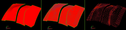
Render modes. Left to right; solid, solid with wireframe mesh, and wireframe mesh only. click to enlarge
Render Side (3D mesh only) Display it with tetrahedrons on either side 1 (above), side 2 (below) or both sides of the surface.
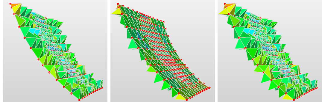
Render side. Left to right; side 1, side 2, side 1 and 2 simultaneously. click to enlarge
Top and Base Layers Visible (3D grid only) Show the top and base layers.
Reset Boundaries Reset the boundaries of the fault.
Hanging Wall (3D grid only) Display the hanging wall side of the fault.
Foot Wall (3D grid only) Display the footwall side of the fault.
Both (3D grid only) Display both sides of the faults transparently. This can for example be used to visualize fault juxtaposition (when combined with displaying an appropriate property).
Transparency Make it semi-transparent. Adjust the opacity value from the Property Inspector.
Lighting Turn a lighting effect on or off. The lighting effect can enhance the visibility of contours.
Contours Show or hide contour lines relating to the display of properties on a grid or surface.
Contour Labels Show labels on contour lines.
Contouring Options Open the Contouring Options form to specify a wide range of contouring settings.
Interpolation This display setting affects the (color) interpolation of the object displayed in your view. Without interpolation, the color boundaries are sharp; with interpolation switched on, the boundaries are smoothed.
Create
Create Point Set (Only for 3D Mesh) Create two point sets from the surface, one for each side of the surface. Useful to QC properties at either side of the surface, e.g. discontinuous pore pressure across a fault. In the 'Select Properties' dialog that opens, select the properties that you want to have available on the point set. Only nodal properties are available for selection. The point set will be placed in the Data folder.
Create Tri-mesh Create a tri-mesh from the surface. For surfaces in a 3D mesh, two tri-meshes will be created, one for each side of the surface (useful to QC properties at either side of the surface). Select the properties that you want to have available on the two tri-meshes from the 'Select Properties' dialog. The tri-mesh(es) will be placed in the Data folder.
Create Node Side Property From Surface (Only for 3D Mesh) Create a property with property classes indicative for the side of the surface where the nodes are located (side 1, side 2 or shared). Use the Object Inspector  to display the classes.
Create Element Side Property From Surface (Only for 3D Mesh) Create a property with property classes indicative for the side of the surface where the elements are located (side 1 or side 2). Use the Object Inspector to display the classes.
3D View Camera
Focus on Surface Normal Reorients the camera to look perpendicular to the selected surface, i.e., along the surface normal. If the selected surface is not yet visible, it will be toggled on as well.
View History Open the Audit Trail to view a history of changes, including user name, date, context, workflow process, workflow panel, and description. For more on the Audit Trail, see Using the audit trail.