Using the Area Tool
With the Area Tool (Workspace >Tools > Area Tool) you can create a new area, or select an existing area to adjust. The area defines the geometrical settings (lateral and vertical dimensions with a step size) which can be used for data resolution and grid orientation for any resampling done in the application.
You can derive the dimensions of your area based on existing domain objects in your solution, such as an existing models, a grid, polyline set, seismic interpretation, etc.
To create or adjust an area
- From the Area drop-down list, select Create New and enter a name in the adjacent field. You can also select an area to edit.
-
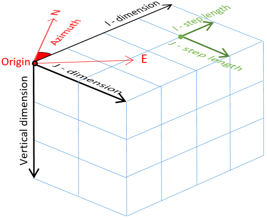
In the lower part of the form, specify the Origin, Dimension, Step Length (grid cell size in case of a grid) and Number of Steps (i.e. number of cells in case of a grid) attributes of the area.
Origin (Easting, Northing, TVDSS, Azimuth(GN)) The northing and easting location values specify the origin of the grid. Adjusting these values moves the area laterally. Adjusting the TVDSS value causes the grid to move vertically, and changing the azimuth (angle with the Northing direction) rotates the area. Use the axis in the lower left corner of the 3D View for reference when adjusting northing and easting values.
Dimension (I, J, Vertical) Adjusts the size of the area laterally for the I and J values and vertically for the depth value.
Step length (I, J) Adjusts the internal resolution (cell size in case of a grid) in both the I and J directions.
Number of Steps (I, J) Specifies the number of steps (cells in case of a grid) to be contained in the I and J slices of the Area. When you change the number of steps, the dimension of the model is adjusted.
Keep lateral cell dimensions when resizing area This option applies to the graphical editing of the area in the 3D View. When selected, the lateral cell dimensions are retained and changing the area in a lateral direction changes the number of cells in that direction. When not selected, the number of cells in the lateral direction is retained, and changing the area in a lateral direction changes the cell dimension in that direction.
- Use the Autofill Parameters option to create an area box based on the selection you make on the Autofill Parameters form. You can select to derive your settings from all data types which have an internal resolution:
- Structural model - Select a structural model to derive the area from; the data used to create the structural model and the modeling parameters specified for the structural model are used to create the area.
- Fault model - Select a fault model to derive the area from; the data used to create the fault model and the modeling parameters specified for the fault model are used to create the area.
- 2D Grid - To use a 2D grid to calculate the area, first select the model containing the 2D grid of interest, then select the 2D grid. The azimuth and the step sizes will be copied from the grid object.
- 3D Grid - Select a 3D grid to derive the area from. The azimuth and the step sizes will be copied from the grid object.
- Polyline set - To use a polyline set to calculate the area, first select the model containing the polyline set of interest, then select the polyline set.
- Surface set - Select a surface set to derive the area from.
- Seismic survey - From the list of available surveys, select the seismic survey you want to derive the area from.
- 3D Mesh structural model - Select a 3D mesh structural model to derive the area from; the data used to create the 3D mesh structural model are used to create the area. Be aware that for the 3D mesh structural model you have to manually specify the azimuth.
- Click OK to create or update the area and close the form, or click Apply to create the area and keep the Area Tool form open. In either case, the calculated area box appears in your 3D View, and is available in the JewelExplorer under the Area folder.