About caliper data and interpretation
When drilling wells, knowing the state of stresses is essential. The state of stress has direct application to problems of wellbore stability, reservoir performance and hydrocarbon migration. The analysis of compressive wellbore failure (breakouts) provides information that is needed to constrain the full stress tensor.
Stress-induced wellbore breakouts form symmetrically on opposite sides of a wellbore due to compressive failure in the region of maximum compressive hoop stress when the maximum stress concentration around the borehole exceeds the compressive strength of the rock.
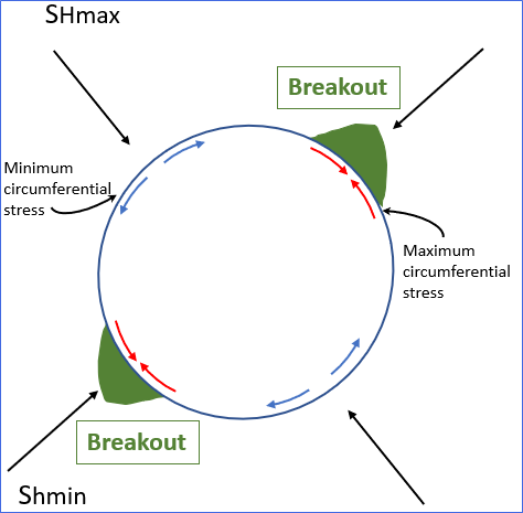
Schematic image of a vertical well showing wellbore section with breakouts click to enlarge
In a vertical well, the zone of failure is centered at the azimuth of the minimum horizontal far-field stress. Consequently, one can directly deduce the orientation of the in-situ stress tensor from the observation of breakouts (Plumb and Hickman, 1985; Zoback et al., 1985). In inclined wells, or in wells where one principal stress axis is not parallel to the wellbore axis, the location of breakouts is a complex function of the orientation of the wellbore and the orientations and magnitudes of the in-situ stresses (Peska and Zoback, 1995). A rotation of breakouts with depth may be observed in wells that intersect active shear planes (Shamir and Zoback, 1992; Barton and Zoback, 1994). These planes are often highly permeable in both the strike and dip direction (Barton et al., 1995). The difficulties associated with using caliper data to identify breakouts are often underappreciated. It is important to distinguish breakouts from other stress induced or drilling-induced enlargements such as washouts and keyseats. Washouts generally occur when breakouts become so wide that the remaining intact borehole surface is not sufficient to maintain wellbore integrity and the entire hole becomes enlarged. Pipe wear or other drilling-related wellbore damage causes keyseats, generally observed as asymmetrical borehole enlargement. Failure to apply strict criteria for breakout identification when using caliper data can result in the misinterpretation of washouts and keyseats as wellbore breakouts.
Four-Arm Caliper Data
Four-arm caliper tools record two perpendicular borehole diameters.
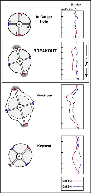
Schematic image of a 4 arms caliper logs and interpretations of the borehole geometry click to enlarge
The following list summarizes the criteria used to distinguish stress-induced wellbore breakouts from other features such as washouts and keyseats in four arm caliper data:
- The tool should rotate when not in a breakout.
- When the caliper tool encounters a breakout, the tool should stop rotating in the well, because one caliper arm pair is engaged in the breakout.
- The small diameter measured by the caliper must be equal to the bit size, and the large diameter must be larger than the bit size.
- In the case of an inclined well, the orientation of the wellbore enlargement should not be the same as the orientation of the wellbore deviation. Otherwise, the elongation is likely to be a keyseat.
- Neither caliper diameter should be smaller than the bit size, which can occur in zones of keyseats due to an off-centered tool (a chord that does not include the center of a circle is smaller than the circle’s diameter).
Six-Arm Caliper Data
The interpretation of six-arm caliper data for breakout identification is more complicated than the interpretation of four-arm data. Data is reported as six individual borehole radii, the center of the tool is commonly not aligned with the borehole axis (see schematic image below), and the 60° angular distance between pads frequently allows two adjacent pads to be engaged in an enlargement, with neither pad at the center of the enlargement.
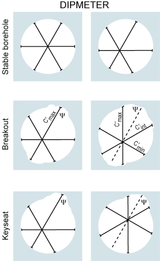
Schematic image of a 6 arms caliper and interpretations of the borehole geometry (after Jarosinski and Zoback, 1998; Jarosinski 1998). The borehole elongation direction is denoted by the dashed line, labeled ψ click to enlarge
The interpretation of six-arm caliper data is described in detail by Jarosinski and Zoback (1998), who determined that the following criteria may be used to distinguish stress-induced wellbore breakouts from other features, such as washouts and keyseats, in six-arm caliper data:
- Borehole shape should indicate symmetrical borehole enlargements.
- The smallest diameter measured by the caliper should be equal to or less than the bit size.
- In the case of an inclined well, the direction of wellbore enlargement should not be the same as the direction of wellbore deviation.
References:
Barton, C., and M. D. Zoback, 1994. Stress perturbations associated with active faults penetrated by boreholes: Possible evidence for near-complete stress drop and a new technique for stress magnitude measurements, J. Geophys. Res., v. 99, pp. 9,373–9,390.
Barton, C. A., M. D. Zoback, and D. Moos, 1995. Fluid flow along potentially active faults in crystalline rock, Geology, v. 23, pp. 683–686.
Jarosinski, M., and M. D. Zoback, 1998. Comparison of six-arm caliper and borehole televiewer data for detection of stress induced wellbore breakouts: application to six wells in the Polish Carpathians, pp. F8-1–F8-23 + 12 figures.
Peska, P., and M. D. Zoback, 1995. Compressive and tensile failure of inclined wellbores and direct determination of in situ stress and rock strength, J. Geophys. Res., v. 100, pp. 12,791– 12,811.
Plumb, R. B., and S. H. Hickman, 1985. Stress induced borehole elongation: a comparison between the four-arm dipmeter and borehole televiewer in the Auburn geothermal well, J. Geophys. Res., v. 90, pp. 5,513–5,521.
Shamir, G., and M. D. Zoback, 1992. Stress orientation profile to 3.5 km depth near the San Andreas Fault at Cajon Pass, California, J. Geophys. Res., v. 97, pp. 5,059–5,080.