Six-arm caliper analysis
Differences in the design of the six-arm dipmeter tool compared to the four-arm tool require a different methodology for breakout analysis (Jarosinski and Zoback, 1998; Jarosinski, 1998).
The four-arm dipmeter tool has coupled, conjugate arms. The caliper length is measured by the combined lengths of opposing arms, and the tool is assumed to stay centered between opposing pads (see image below, C, F, and I).
The independent hinge of the six-arm dipmeter does not guarantee tool centralization; i.e., the axis of the tool may not coincide with the borehole axis (see image below, B, D, and G). The tool rotates easily and does not necessarily stop its rotation within shallow enlargements. The 60° angular distance between adjacent arms often allows two pads to be engaged in a wide breakout, in which case the orientation of the maximum caliper cannot be taken as the direction of borehole elongation (see image below, E). The independent hinge allows you to differentiate between symmetrical (breakout) and asymmetrical (keyseat) borehole elongations, making it possible to identify breakouts that correlate with the azimuth of deviated wells. This distinction is not possible with the four-arm dipmeter.
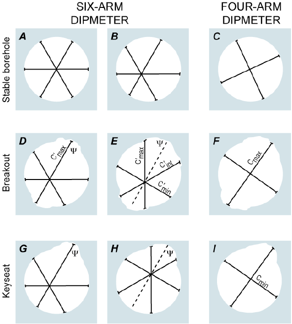
Schematic image of a 6 arms and 4 arms caliper tool and interpretations of the borehole geometry (after Jarosinski and Zoback, 1998; Jarosinski 1998). The borehole elongation direction is denoted by the dashed line, labeled ψ. Note that the caliper measures shown in the six-arm examples are different from the corrected caliper lengths. click to enlarge