Faulted unconformities
When your fault model contains one or more unconformities, the model validation at the end of your fault modeling workflow checks whether your unconformity is geometrically consistent. The unconformities in the fault model cannot be faulted or discontinuous, see How to model an unconformity. This condition is tested using Model Validation (model > Faults > Fault Modeling), which does not further specify the exact location of a detected issue.
The diagnostic tool picks up the results and visualizes the exact location of the issue in a dedicated view. An example is shown below. The model validation complains about the unconformity BCU to be faulted. You cannot use the fault model in a 3D structural model unless the issue is resolved.
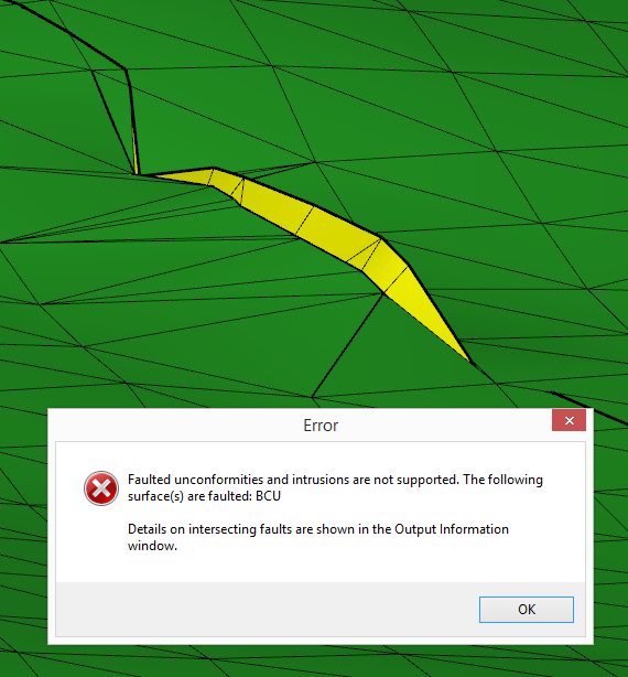
Running Model Validation resulted in an issue: the green unconformity is faulted by the yellow fault. click to enlarge
The Diagnostic Tool can pick up the results of the Model Validation, and provides visual feedback in the dedicated Diagnostic View. The example below shows the green unconformity to be cut and offset by the yellow fault.
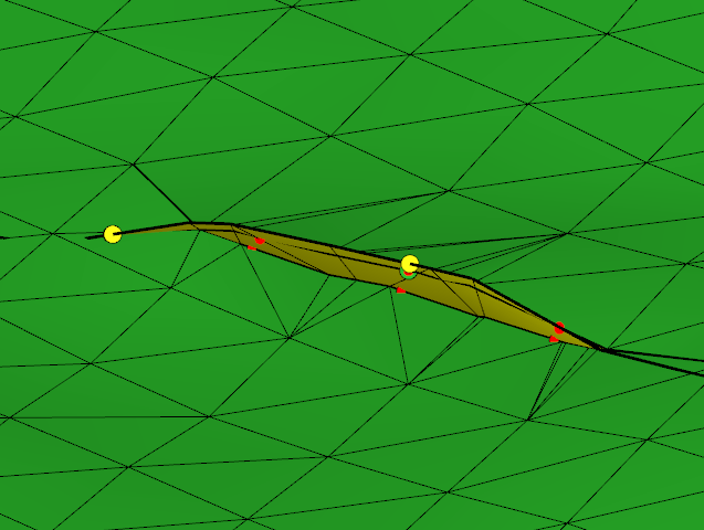
Annotated location of the faulted unconformity as reported by the Diagnostic Tool. click to enlarge
You may solve the issue by different means, depending on your modeling context and strategy. In both scenarios you need to re-run the Model Validation step to check on the results.
- If you require a faulted unconformity, you need to remove it from your fault model and specify it only in your stratigraphic model. This may require you to run the Solve fault intersections step again.
- If you want to keep the unconformity in your fault model to achieve high-quality truncations of the layering against the unconformity, you need to provide a laterally consistent and continuous unconformity. For the example shown you can use the editing tools on the two tri-meshes or revisit the Solve fault intersections step.
Solving the issue using the editing tools
First, the green tri-mesh in the location of the offset is cleaned. You can remove the triangles adjacent to the offset with the Remove Triangles Under Line tool.
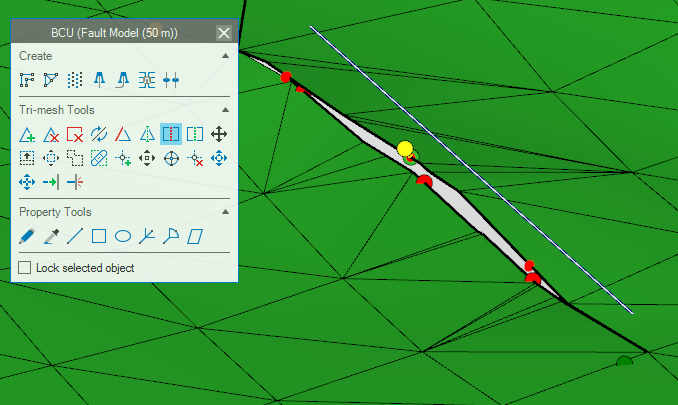
The location where the offset is present in the tri-mesh needs to be cleared. This can be done with the Remove Triangle Under Line tool. click to enlarge
After the triangles in the direct proximity are removed, you can use the Fill Hole tool to close the gap again.
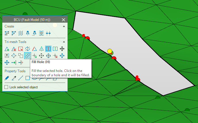
The created hole can be filled with the Fill Hole tool. click to enlarge
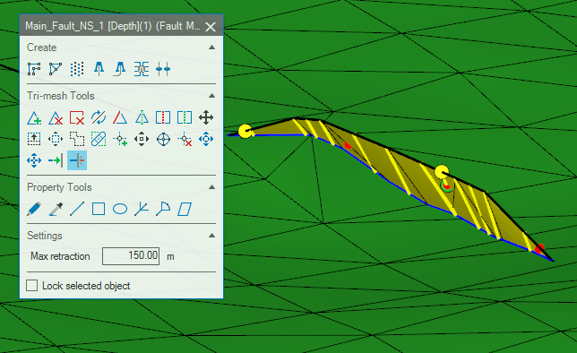
After the unconformity is filled, you can retract the fault against the unconformity. You must re-run the Model Validation step to verify the results and consistency of your fault model. click to enlarge