Intersection quality
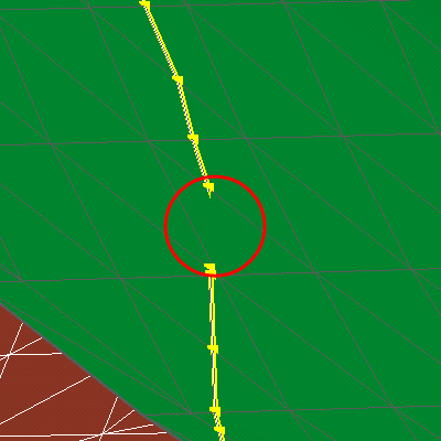
An intersection between two fault surface in which there is a free boundary section. The orange nodes and segments depict the unresolved section while the yellow nodes show watertight sections. click to enlarge
The fault model is a fundamental building block for the 3D structural model as well as the 3D grid. The segmentation of the model space relies on a consistent fault model in which the contacts between the faults have been resolved and clear intersection relationships are present. The intersection quality test provides visual information on the boundaries of your faults. Checking every single boundary of your fault model, it reports whether free nodes or watertight nodes have been encountered and color codes the boundary accordingly. A free node has no apparent contact with another surface. Free nodes and corresponding sections are highlighted in orange.
Yellow nodes and lines mark true watertight sections. You must review any sections marked in orange. These are either remaining holes or sections in which parts of one fault stick through another fault. Holes may lead to horizons leaking through the fault system. Faults sticking through other faults may produce very mall ghost compartments. Some geometrical inconsistency can be handled by successive algorithms so not all issues will generate artifacts.
Solving the issue using the (editing) tools
To resolve the issue there are multiple possibilities. Preferentially you should try to solve the fault intersections again and review the results. For small local adjustments, you can use the tri-mesh editing tools. Local tool-driven extension  and retraction
  as well as the movement of single nodes
  can be applied to resolve the issue.
Be aware in which modeling step you make your changes. If you apply them to the input surfaces of your fault model, you have to repeat the successive workflow steps to propagate the changes in your fault model.