Graphically editing properties
You can graphically edit an object's property in the 3D View. You can do this using the Property Editing tools provided on the floating palette. The floating palette of the graphical property editing tools contains a Settings section where you specify the editing values and where you control the direction, range and shape of the edited area or grid cells.
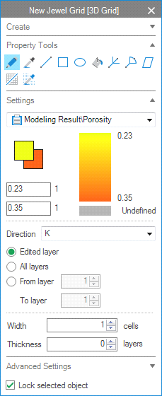
Example of the settings section of the floating palette. The selected property is Porosity, with values in the model ranging from 23% to 35%. The foreground value is arbitrary set to 18% (background value is 35%). click to enlarge
Once you have selected the property tool that you want to use, the Settings section opens in the floating palette. First, you select the property that you want to edit from the drop-down menu. The color scale bar then automatically updates with the property values of your object. Next to the color scale bar, there are 2 fields where you can manually fill in the values you want to use for editing: a foreground value (the upper field in the Settings section) and a background value (the lower field in the Settings section). You can easily change the values by left clicking (for the foreground value) or right-clicking (for the background value) in the color scale bar of the Settings section, or in the gray square below the scale bar (value is Undefined). You can also type any value in one of the two fields and press tab on your keyboard.
Directional editing
Directional editing is available when you are editing properties on a 3D grid (as opposed to editing properties on a surface or tri-mesh). It allows you to edit parts or complete slices/layers in the direction of your choice. To do this, select your preferred direction (K, I, J or View angle) from the Direction drop-down menu of the Settings section, in combination with one of the available options:
- When you select K, I or J, the three options, Edited layer/slice (to edit only the layer/slice that you click/draw on), All layers/slices (to edit all layers/ slices in your chosen direction) and the From layer/To layer (to edit a specific range of layers/slices in your chosen direction) are available. Also, the Stop at discontinuity check box becomes available, which enables you to limit the edited layer/slice to the grid segment that you are working on, for example, when it is bounded by a fault.
- When you select View angle, the Visible cells and the All cells options become available. The All cells option enables you to edit all cells that lie along the axis of your view, from the point where you click until the last slice/layer at the outermost end of your grid. With the Width option you can specify the width around the cell(s) that you select.
When editing properties of point sets, polylines, 2D grids or tri-meshes (for example depth), the Settings section of the floating palette is less extensive than when editing 3D grids, and consists of depth and width related functionality. Directional editing options are not available.
Advanced settings
The Advanced Settings section of the floating palette provides the option to filter on property classes such as geometrical directions, zones, or any other discrete property class in your model. Open the Advanced Settings section and choose a discrete property from the Filter discrete property drop-down menu. Checking a property class from the list will ensure that only cells which have this property class will be affected while editing.
 Pencil Use this to edit the selected triangle, area or cell (or a range of cells) in the 3D grid with a property value of your choice. Instead of editing just one node, triangle or cell, you can also draw an arbitrary line on your surface or 3D grid and immediately apply the foreground or background value to the cells under that line. To use the tool:
- In the 3D View, visualize the surface, tri-mesh or 3D grid that you want to edit. Select the pencil icon; a Settings section opens in the floating palette.
- From the drop-down list in the Settings section, select the property that you want to edit. Enter the foreground and background values of your choice (explained in the introduction of this topic).
- Left-click on a cell in your grid to apply the foreground value; to apply the background value, right-click on a cell in your grid. Note that if you click on a single node or a grid block the thickness and width values are not used to edit selected property. In this case, the effective change is observed only for the node or the grid block.
- Optionally: editing a complete slice/layer in the I, J or K direction (3D grid only)
- Optionally, edit under an arbitrary line
- Drawing a line on a 3D grid: on the Settings section of the floating palette, the Width and Thickness options are available. The width is defined as the number of cells impacted on the layer/slice that you draw on; the thickness is defined as the number of slices/layers impacted perpendicular to the slice that you draw on. This is easiest to understand when you imagine drawing a channel on a k layer; the width represents the channel width, the thickness represents the channel depth. Note that when you fill in Width = 0, no area around the line is calculated and only the cells under the line, are edited. As soon as you enter Width = 1 (or any higher value), an orange/brown area appears around your line while drawing, and any cell hit by the orange/brown area will be edited.
- Drawing a line on a surface representation (2D grid or tri-mesh): on the Settings section of the floating palette, the Width option is available. The width is defined in terms of horizontal or planar thickness of the line.
Choose the All layers/slices (to edit all layers/slices) or the From layer/To layer (to edit a specific range of layers/slices) when you want to edit complete layers/slices with one click. You have to specify the direction I, J or K from the Direction drop-down menu to set the direction in which the complete layer/slice will be edited.
You can edit values under an arbitrary line. To do so, press and hold the Ctrl key and draw the line on your grid (left-click and draw to apply the foreground value, right-click and draw to apply the background value).
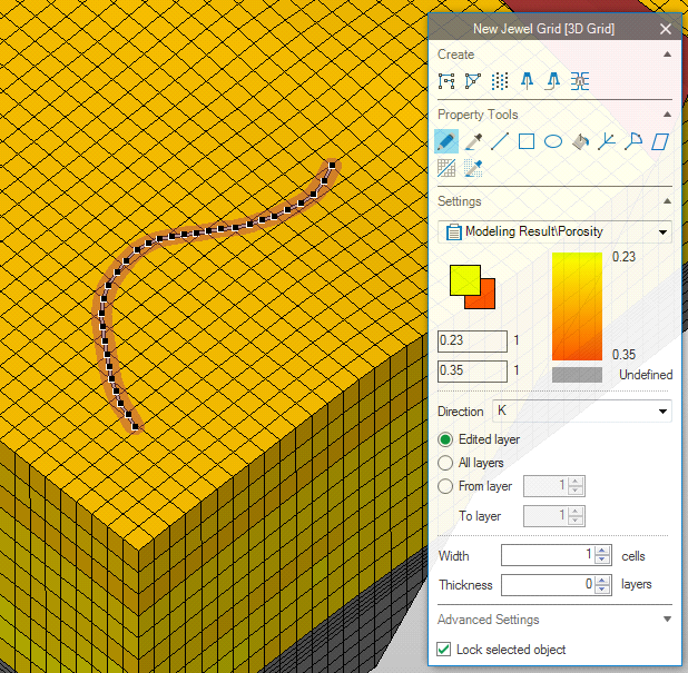
Example of the use of the Width option: the value entered defines the width of the orange/brown area around the line (in the example, the value is set to 1); any cell hit with the orange/brown area will be edited click to enlarge
 Color Picker Use this to select a property value from your surface, triangle or grid cell as editing value. You can pick two values, a foreground value and a background value. To use the tool:
- In the 3D View, visualize the surface, tri-mesh or 3D grid that you want to edit. Select the Color Picker icon; the Settings section opens in the floating palette.
- From the drop-down list in the Settings section, select the property that you want to work on.
- Left-click the surface, triangle or grid cell in the 3D view to pick the foreground value; right-click to pick the background value.
- The selected property values will now be used as foreground or background value in the settings section of the floating palette.
 Line Use this to assign a property value under a line. You can specify the width of the edited area, and (in 3D grid editing only) the number of slices/layers edited under the line. You can create a straight line, a zig-zag line or a smooth line. To use the tool:
- In the 3D View, visualize the surface, tri-mesh or 3D grid that you want to edit. Select the Line icon; the Settings section opens in the floating palette.
- From the drop-down list in the Settings section, select the property that you want to edit. Enter the foreground and background values of your choice (explained in the introduction of this topic).
- Optionally, when drawing on a 3D grid, the floating palette provides for directional editing, and Advanced Settings, which are explained in the introduction of this topic.
- Set the Width (and Thickness when editing on a 3D grid) of your line:
- When editing on a surface representation (2D grid or tri-mesh), the width is defined as the area around the line (in ft or m) and visible as an orange/brown area while drawing. Note that the Width has to be at least the distance between nodes, or the width of a triangle, to take effect.
- When editing on a 3D grid, the width is defined as the number of cells edited on the layer/slice that you draw on. Note that when you fill in Width = 0, no area around the line is calculated and only the cells directly in contact with the line, are edited. As soon as you enter Width = 1 (or any higher value), an orange/brown area appears around your line and any cell hit by the orange/brown area will be edited.
- Click subsequently on your surface, triangles or grid cells in your 3D view; each click creates a new point on the line.
- Double-click to finalize the line: left-double-click will apply the foreground value, right-double-click will apply the background value.
- Optionally, you can press Ctrl (after you clicked the starting point of your line) to produce a smooth line. Note that when you have pressed the Ctrl key, smoothing functionality is switched on, and every line you draw will be smooth. To switch smoothing off, press the Ctrl key again.
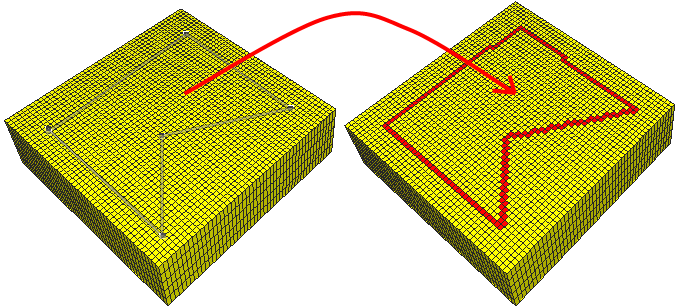
Creating an object with the line function (red cells) click to enlarge
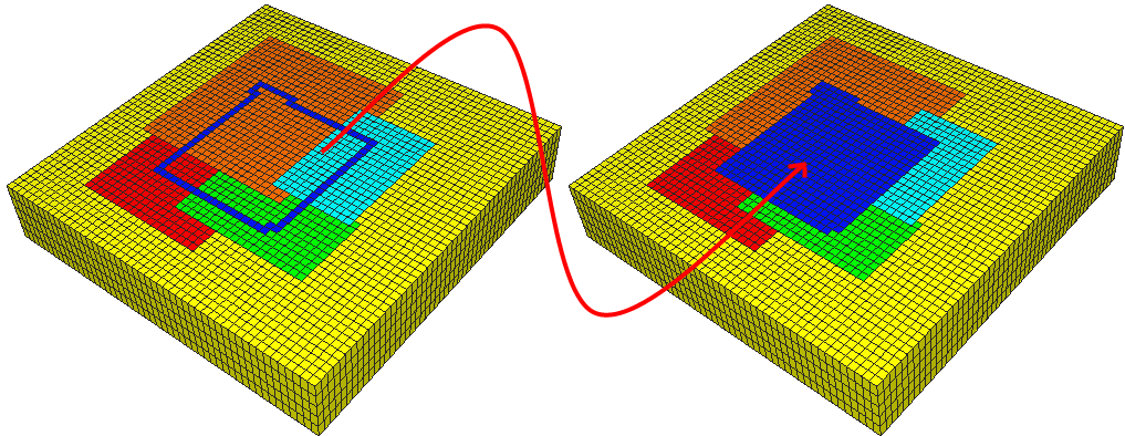
 Square Use this to edit property values within a square or to edit property values at the border of a square. The orientation of the square is along the K, I or J direction. To use the tool:
- In the 3D view, visualize the surface, tri-mesh or 3D grid that you want to edit. Select the Square icon; the Settings section opens in the floating palette.
- From the drop-down list in the Settings section, select the property that you want to edit. Enter the foreground and background values of your choice (explained in the introduction of this topic).
- Optionally, when drawing on a 3D grid, you can use directional editing and Advanced Settings, both which are explained in the introduction of this topic.
-
Click in the 3D View to locate the upper left corner of your square; click again to locate the lower right corner of you square: left clicking the lower right corner applies the foreground value, right clicking the lower right corner applies the background value.
Optionally, you can edit only the border of your square. The width of the border is the node distance, triangle width or cell width, depending on the object you work on. To do so, press the Ctrl key after you have located the first corner of your square. You can switch back to fill mode by pressing Ctrl after clicking the first corner location of the next square.
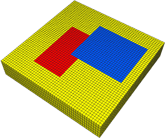

Solid squares created with square function (red and blue cells) click to enlarge
 Ellipse Use this to edit property values under a specified ellipse. To use the tool:
- In the 3D view, visualize the surface, tri-mesh or 3D grid that you want to edit. Select the Ellipse icon; the Settings section opens in the floating palette.
- From the drop-down list in the Settings section, select the property that you want to edit. Enter the foreground and background values of your choice (explained in the introduction of this topic).
- Optionally, when drawing on a 3D grid, you can use directional editing and Advanced Settings, both which are explained in the introduction of this topic.
- Click on your grid to locate the center of the ellipse.
- Drag to define the length and direction of the first axis.
- Click again to apply step 5 and to switch to define the second axis. Once finished, double-click and the ellipse will be created: left-double-click will apply the foreground value, right-double-click will apply the background value.
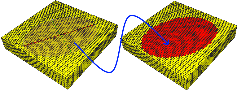
click to enlarge
 Filler (3D grid and 3D mesh only) Use this to edit the property values of the cell you click, a whole slice/layer you click, or all neighboring cells with the same current value as the cell you click: for the latter option, you can give a value range within which the connected cells have to fall. To use the tool:
- In the 3D View, visualize the 3D grid or the 3D mesh that you want to edit. Select the Filler icon; the Settings section opens in the floating palette.
- From the drop-down list in the Settings section, select the property that you want to edit. Enter the foreground and background values of your choice (explained in the introduction of this topic).
- Optionally, you can use directional editing and Advanced Settings, both which are explained in the introduction of this topic.
- You have three options how to fill a cell/range of cells:
- With the 'Used picked value as filter value' switched off (checked) but the Range set to 0, all neighboring cells will be edited (left mouse click applies the foreground value; right mouse click applies the background value).
- With the 'Use picked value as filter value' switched on (checked) and you have a continuous property selected and the Range set to a value, the clicked cell and all connected cells that fall within your range criterion will be edited. The value you enter forms the range around the value of your clicked cell; the higher this value, the more neighboring cells fall within the criterion and the more cells will be edited; the lower the range value, the less neighboring cells fall within the criterion and the less cells will be edited. Note that the calculation of the range (i.e. whether cells fall within the criterion, or not) is related to the Minimum and Maximum set for that property in the Property Catalog (under HOME > Dictionaries > Property Catalog > Property types).
- Left (or right for usage of the background value) click the grid cell you want to edit. Depending on your choice in step 3, other cells around the clicked cell will also be edited.
Fill mode – Boundary constraint (blue area) click to enlarge
 Branched River Delta Use this to draw a branched river delta on your surface, tri-mesh or 3D grid, and edit the property values/grid cells with the foreground or background value. You can specify the dimensions of the branched river delta by choosing its width, angle between branches, and number of branches. To use the tool:
- In the 3D View, visualize the 3D grid that you want to edit. Select the Branched River Delta icon; the Settings section opens in the floating palette.
- From the drop-down list in the Settings section, select the property that you want to edit. Enter the foreground and background values of your choice (explained in the introduction of this topic).
- Optionally, when drawing on a 3D grid, you can use directional editing and Advanced Settings, both which are explained in the introduction of this topic.
- Enter the width (and thickness if available) of your branches:
- Drawing on a 3D grid: The width is defined as the number of cells impacted on the layer/slice that you draw on. Note that when you fill in Width = 0, no area around the branches is calculated and only the cells directly under the branches, are edited. As soon as you enter Width = 1 (or any higher value), an orange/brown area appears around your branches while drawing and any cell hit by the orange/brown area will be edited.
- Drawing on a surface representation (2D grid or tri-mesh): the width is defined as the area around the line (in ft or m) and visible as an orange/brown area while drawing. Note that the Width has to be at least the distance between nodes, or the width of a triangle, to take effect.
- Enter the angle of delta, which is the angle between the two outermost branches.
- Enter the number of branches of your branched river delta.
-
Click to set the starting point of your delta; drag the mouse in your desired direction and left-double-click to apply the foreground value, right-double-click to apply the background value.
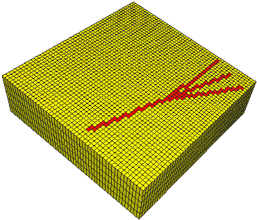

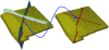
Branched river delta click to enlarge
 Solid River Delta Use this to draw a solid river delta on your surface, tri-mesh or 3D grid, and edit the property values/grid cells with the foreground or background value. You can specify the dimensions of the solid river delta by choosing its width and delta angle.
How to use this tool:
- In the 3D View, visualize the 3D grid that you want to edit. Select the Solid River Delta icon; the Settings section opens in the floating palette.
- From the drop-down list in the Settings section, select the property that you want to edit. Enter the foreground and background values of your choice (explained in the introduction of this topic).
- Optionally, when drawing on a 3D grid, you can use directional editing and Advanced Settings, both which are explained in the introduction of this topic.
- Enter the width (and thickness if available) of your delta:
- Drawing on a 3D grid: The width is defined as the number of cells impacted on the layer/slice that you draw on. Note that when you fill in Width = 0, no area around the branches is calculated and only the cells directly under the branches, are edited. As soon as you enter Width = 1 (or any higher value), an orange/brown area appears around your branches while drawing and any cell hit by the orange/brown area will be edited.
- Drawing on a surface representation (2D grid or tri-mesh): the width is defined as the area around the line (in ft or m) and visible as an orange/brown area while drawing. Note that the Width has to be at least the distance between nodes, or the width of a triangle, to take effect.
- Enter the angle of delta, which is the angle between the two outer edges of the delta.
-
Click to set the starting point of your delta; drag the mouse in your desired direction and left-double-click to apply the foreground value, right-double-click to apply the background value.
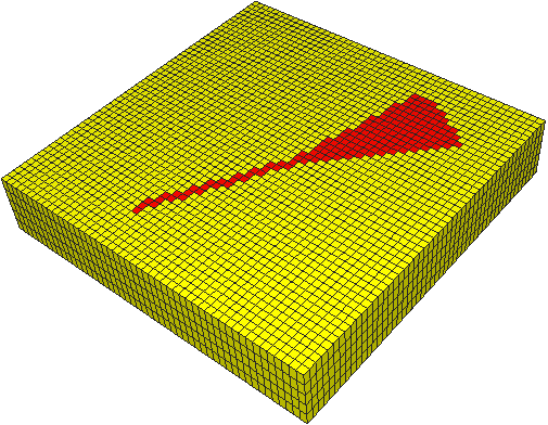

Solid river delta click to enlarge
 Plane Use this to edit cells which intersect the plane. To use the tool:
- In the 3D View, visualize the tri-mesh, 3D grid or 3D mesh that you want to edit. Select the Plane icon; the Settings section opens in the floating palette.
- From the drop-down list in the Settings section, select the property that you want to edit. Enter the foreground and background values of your choice (explained in the introduction of this topic).
- Optionally, the Advanced Settings are available on the editing palette, which are described in the introduction of this topic.
- Click on the 3D grid or the 3D mesh to fix first point of intersection of the plane. Move the second point of intersection to preview the plane and click again to fix the second point.
- To create a vertical plane, left-double-click ends the plane and the foreground value is applied; right-double-click ends the plane and applies the background value.
The width of the edited cells is one grid cell (when working on a 3D grid), one node distance (when working on a 2D grid) or one triangle (when working on a tri-mesh).
- To create a tilted intersecting plane, click again after previewing the vertical plane. A third point of intersection of the plane with the 3D grid or the 3D mesh will modify the tilt of the plane. Left click to end the plane and apply the foreground value; right click to end the plane and apply the background value.
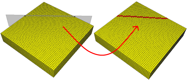
Edit cells intersected by a plane click to enlarge
 Tri-mesh (3D grid only) Use this to edit the property values of all cells intersected by a tri-mesh: this can be a fault, or a surface parallel tri-mesh. To use the tool:
- In the 3D View, visualize the 3D grid that you want to edit, as well as the intersecting tri-mesh. Select the Tri-mesh icon; the Settings section opens in the floating palette.
- From the drop-down list in the Settings section, select the property that you want to edit. Enter the foreground and background values of your choice (explained in the introduction of this topic).
- Optionally, the Advanced Settings are available on the editing palette, which are described in the introduction of this topic.
- Click the tri-mesh; the cells that are intersecting with the tri-mesh will be edited. Left mouse click applies the foreground value, right mouse click applies the background value.
-
If necessary, turn off the visibility of the tri-mesh and see the results.

Edit cells intersected by a tri-mesh click to enlarge
 Filter Value Picker (3D grid and 3D mesh only) Use this to graphically select a discrete property class, or to determine to which discrete property class a grid cell belongs, while having that, or different property visualized in the 3D View. For example, when a porosity grid property is visualized in the 3D View, and you want to determine to which Fluids class (oil, gas or water) a certain porosity cell belongs and/or you want to select that Fluids class as a filter, click on the porosity grid cell (while having 'Fluids' selected in the floating palette) and the associated Fluids class will be selected from the Fluids class list (for example 'gas'). To use the tool:
- In your 3D View, visualize the property grid that you want to click on/use for cell selection. Note that this can be a different property (for example you have visualized porosity), than the one which you want to investigate/select as filter (for example Fluids).
- Select the Filter Value Picker icon; the Settings section opens in the floating palette.
- From the Filter discrete property drop-down list, select the discrete property that you want to investigate and/or use as filter (for example Fluids).
- Uncheck all the check boxes in the list of property classes (for example oil, gas, water). You can also use the context menu to do this: right click in the list and select Select none.
- Click in the 3D View on a cell: the associated property class is selected in the list of property classes (for example gas). You can now use this property class as a filter.