Tri-mesh context menu
Show / Hide Fault Polylines Show or hide the related polyline set.
Show Connected Surfaces Show all surfaces that are connected to the selected tri-mesh in your 3D View.
Show Intersections Highlight all the intersections that are connected to the selected tri-mesh in your 3D View.
Hide (Only for context menu in a view) Hide it in your view.
Show Legend Show or hide a legend for it in your 3D View.
Display Settings
Color Pick a color to display it in the view.
Mesh Color Pick the color to be used to display the mesh.
Render Mode Display it as a solid surface, as a wireframe, or as a solid surface with wireframe mesh. For a surface in a 3D mesh model, you can also select to display as a solid surface with wireframe mesh and nodes, as a solid surface with nodes, as a wireframe, as a wireframe with nodes or as nodes only.
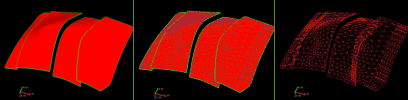
Render modes. Left to right; solid, solid with wireframe mesh, and wireframe mesh only. click to enlarge
Transparency Make it semi-transparent. Adjust the opacity value from the Property Inspector.
Lighting Turn a lighting effect on or off. The lighting effect can enhance the visibility of contours.
Contours Show or hide contour lines.
Contour Labels Show labels on contour lines.
Contouring Options Open the Contouring Options form to specify a wide range of contouring settings.
Interpolation This display setting affects the (color) interpolation of the object displayed in your view. Without interpolation, the color boundaries are sharp; with interpolation switched on, the boundaries are smoothed.
Colorset Blending Choose between default and blended colorsets. Blended means that the full colorset range is used to render from one value to the next value, so that you do not lose resolution due to discrete steps in data.
Edit... Edit the tri-mesh manually. On the Tri-mesh form, you can adjust any of the data values you wish and take full control of your surface.
Create
Create Point Set Create a point set from the tri-mesh data.
Create Boundary Create a boundary from the tri-mesh data.
Create Intersection Polyline Set Create a polyline set from the intersection between tri-meshes. Select the tri-meshes in the JewelExplorer. You can select any number of tri-meshes; for each intersection a separate polyline set is created.
Create Intersection with Cross Section Create a polyline set from the intersection between the tri-mesh and a cross section.
Create Surface-parallel Section Create a surface parallel cross section from the tri-mesh.
Properties
Set Active Property Select a property for display in the 3D View. You can also select properties to view using the visibility checkboxes in the JewelExplorer.
Property Table... View a table showing statistical information on all its properties. Select multiple items in the JewelExplorer, right click on one of them to open its context menu and select this item to display the properties of all those items at once in the table. For more on this, see Property table.
Default Geometry Properties
Opens a predefined list with properties. When you select a property, the values for this property are calculated, the property is added to the JewelExplorer and displayed in the active view. If you update the geometry of the object, the property is automatically recalculated. For tri-meshes and 3D meshes, you can choose from multiple mesh quality properties to help you assess the quality of the mesh.
3D View Camera
Focus on Surface Normal Reorients the camera to look perpendicular to the selected surface, i.e., along the surface normal. If the selected surface is not yet visible, it will be toggled on as well.
View History Open the Audit Trail to view a history of changes, including user name, date, context, workflow process, workflow panel, and description. For more on the Audit Trail, see Using the audit trail.
Auxiliary Information
Add Select one of the options to add auxiliary data of the selected type.
File Add information in the form of a file. In the dialog, navigate to the file you want to include and select it. You can include a wide variety of file types, including pdfs, images (*.bmp, *.jpg, *.gif, *.png, *.tif), movie files (*.avi, *.mpg, *.wmv, *.mov, *.qt, *.mp4), Excel™ spreadsheets (*.xls, *.xlsx), Word™ documents (*.doc, *.docx) and PowerPoint™ presentations (*.ppt, *.pptx). Click Open to select it and open the Add Auxiliary Information form.
Note Add a note using the Add Auxiliary Information form. After making a selection and entering the required information, click OK to save your settings and add the note.
Hyperlink Add a hyperlink using the Add Auxiliary Information form. Enter a (descriptive) name for the link and the URL (address). Click OK to save and add the link.
DMS Link Add a link to a DMS solution using the Add Auxiliary Information form. Connect first to DMS, and select a solution from the 'Select a DMS Solution' form. The DMS server url where the DMS solution you selected is stored, shows in the Address field. Enter a (descriptive) title and click OK to save and add the link.
Screen Capture Add a screen capture of your view area using the Add Auxiliary Information form. Enter a (descriptive) title and click OK to save and add the screen capture.
Show Select one of the options to show hidden auxiliary information.
File Show all the files that are available for the selected object.
Note Show all the notes that are available for the selected object.
Hyperlink Show all the hyperlinks that are available for the selected object.
Screen Capture Show all the screen captures for the selected object.
Show All Show all the auxiliary information that is available for the selected object.
Hide Select one of the options to hide auxiliary information.
File Hide all the files that are available for the selected object.
Note Hide all the notes that are available for the selected object.
Hyperlink Hide all the hyperlinks that are available for the selected object.
Screen Capture Hide all the screen captures for the selected object.
Show All Hide all the auxiliary information that is available for the selected object.
Delete Select one of the options to delete auxiliary information.
File Delete all the files that are available for the selected object.
Note Delete all the notes that are available for the selected object.
Hyperlink Delete all the hyperlinks that are available for the selected object.
Screen Capture Delete all the screen captures for the selected object.
Show All Delete all the auxiliary information that is available for the selected object.
For more information on auxiliary data, see Adding auxiliary data.
Report
Intersection overview report Create an overview of intersections. The information is copied to the clipboard.
Export
To joatsurface Export to the JewelSuite tri-mesh format.
To ts Export to a Paradigm GOCAD™ triangulated surfaces (.ts) file. Supports multi-select export of tri-meshes, with each tri-mesh written to its own file.
To xyz ascii Export to an XYZ ASCII format. Supports multi-select export of tri-meshes, with each tri-mesh written to its own file.
To ascii Export to an ASCII file. For details, see Tri-mesh ASCII file format.
To ascii Point Set Export to a point set in ASCII format. For details, see Point set ASCII file format.
To Clipboard Copy the tri-mesh data to the Windows™ clipboard.
Get updates from DMS DMS can hold multiple version of a single object. One of these is always marked as 'Latest'. The latest version represents the final state of an object.
The 'Get Latest' option is only enabled when you have a version of an object that is parallel to the 'Latest' version. Select this option to replace your version with the latest version.
Delete Delete the object from the solution. Depending on the type of object, geometric representations, subfolders or objects it may contain are deleted as well.