Applying stair-step gridding to an existing grid
One of the characteristics of the JewelGrid, resulting from and necessary for the orthogonal gridding, is its ability to accommodate truncated cells that may have any number of corner points. Such cells can occur at horizon-fault or fault-fault intersections, or at intersections between horizons and unconformities/intrusions, when those unconformities/intrusions are assigned to the fault model (see also About unconformities and intrusions). Other modeling software cannot handle such truncated cells, so when you export a JewelGrid to another application, you must 'translate' the grid into a 'normal' grid with grid cells each having eight corner points. You perform stair-step gridding to do this using the Stair-Step Grid tool (model > 3D Grid > Grid from Grid > Stair-Step Grid).
This process redefines the continuous fault planes to stair-step planes and re-grids (part of) the selected grid volume accordingly. During re-gridding, the cell configuration around the fault planes changes. Relevant grid properties can also be converted.
To convert a grid to stair-step gridding
-
Open the Stair-Step Grid tool (model > 3D Grid > Grid from Grid> Stair-Step Grid) and select the grid for which you want to create a stair-step grid from the Select JewelGrid drop-down list.
- Under Select the volume to convert, the entire volume is selected by default. To apply stair-step gridding to part of the volume, specify the lateral extension of the re-gridded volume using the I and J index slider bars. To specify the vertical extent of the stair-step grid, select horizons for the Start surface and End surface or, alternatively, specify the start and end k-layer.
- Under Select segments to convert, select the segments to include. The output grid will only contain the cells of the selected segments.
- Under Select properties to convert, select the properties you want to include in the new stair-stepped grid. If you do not select any properties, the stair-step grid will contain only the standard grid properties, such as geometrical data.
- Under Select layering approach, choose how to handle layering at the fault intersections. When reverse faulting is small, select one of the options under Little or no reverse faulting. No extra layers, allow thick cells to be created is generally the best option because no extra layers are created and the connections between cells are kept. No extra layers, allow empty spaces, produces a grid with comparatively better cell shapes, but with the disadvantage that the flow connection between cells is lost. Generate extra layers where needed under Significant reverse faulting is the best option when reverse faulting is severe. The disadvantage is that extra k-layers are created under the reverse fault. For more on the layering approach options, see Examples of layering approach for a JewelGrid with reverse faulting.
- Check the Smoother discontinuities by adjusting depth checkbox to create slightly smoother discontinuities, although this will require greater attention, especially with respect to the smoothing of unconformities. See also Examples of layering approach for a JewelGrid with reverse faulting.
- To create the stair step grid, click Convert, and then OK to close the form.
- Inspect the Output Information pane to see how any conflicting situations were addressed.
Examples of layering approach for a JewelGrid with reverse faulting
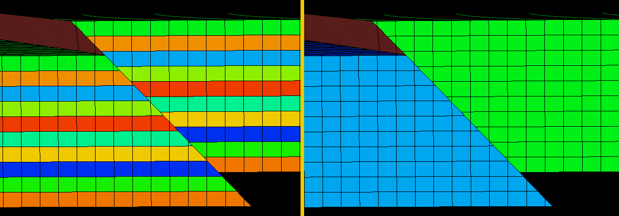
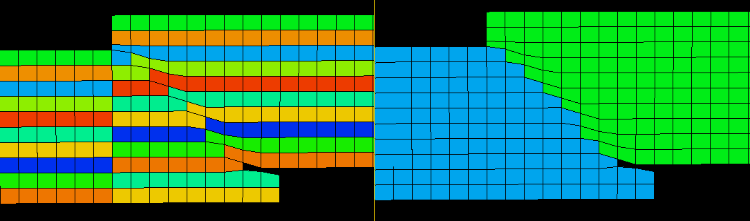
JewelGrid with reverse faulting - k-layers (left) and SegmentID click to enlarge
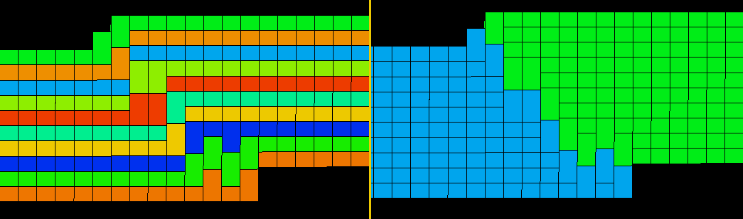
No extra layers, allow thick cells to be created. The best option because no extra layers are created and the connection between cells is maintained click to enlarge
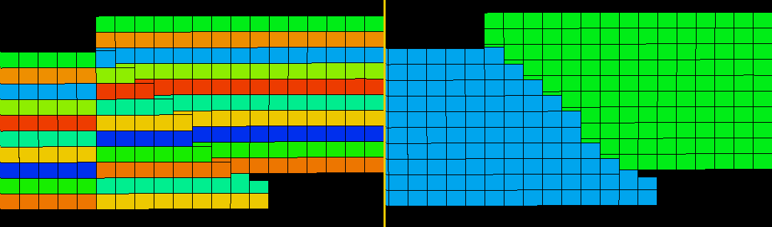
No extra layers, allow empty space between cells. Apply only when reverse faulting is very small. Better cell shape can be achieved, but there is a loss of flow connection between cells click to enlarge
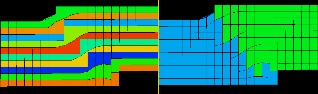
Generate extra layers when needed is the best option for severe reversed faulting, but extra k-layers are created under the reverse fault. One layer is split into two different k-layers click to enlarge
No extra layers, allow thick cells to be created, smooth discontinuities by adjusting depth. Smoothing discontinuities by adjusting depth creates slightly smoother discontinuities, but needs some more attention particularly when smoothing unconformities. click to enlarge
No extra layers, allow empty space between cells, smooth discontinuities by adjusting depth click to enlarge
Generate extra layers where needed, smooth discontinuities by adjusting depth click to enlarge