Specifying mesh options
After creating a 3D mesh volume, you can use the Mesh Options form (model > 3D Meshing) to prepare the mesh for specific objectives during geomechanical simulation:
- Use second order - to create a second order mesh.
- Allow discontinuous properties - to allow sharp transitions (of properties) at compartment boundaries during simulation.
- Split along selected surfaces - to prepare the mesh for slipping ('moving') surfaces.
- If you select option a and/or b, you cannot select option c (it will be grayed out on the form). Also, if you select option c, you cannot select option a and/or b (they will be grayed out on the form). Option a and/or b cannot be applied to the same 3D Mesh as option c.
- When you select Duplicate model at the base of the form, the option is applied to a new (auto-generated) 3D Mesh (with -Copy printed behind its name) which leaves the original 3D Mesh unchanged.
To specify mesh options
- At the top of the Mesh Options form, select the 3D volume mesh to which you want to apply mesh options.
- Select one of the following mesh options:
- This option is closely related to the model > Geomechanics > Surface Properties form. Make sure to define surface properties there for each surface you split, because split surfaces without surface properties will lead to simulation errors.
- The uppermost surface (the one forming the top mesh boundary) cannot be split and will not appear for selection in the 'Surfaces' table on the form.
- Of the surface edges, only the top edge of a surface ending at the top horizon is split; all other surface edges (i.e. surfaces ending at the side or bottom mesh boundaries and surfaces ending at other surfaces) are never split. For a graphical overview of the rules for split surfaces, see images below. To visually QC the split surfaces, use the Visualize Split Nodes form.
- Under Apply Changes To at the base of the form, select Duplicate model is you want the mesh options to be applied to an auto-generated duplicate of the model ('Copy' will be added to its name) in order to keep an unchanged version, or to directly apply the mesh options to the selected 3D Mesh (select Existing model). In the latter case, the selected 3D Mesh will be overwritten and you will not be able to revert back to it.
- Click Apply or OK to create the 3D mesh.
Use second order Check this box if you want to create a second-order mesh. Additional nodes will be created and added at the mid-points of each edge. As these nodes can carry information (e.g. pressure), you can typically produce a more detailed simulation, but at the expense of computing power.
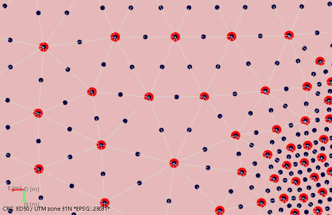
First order mesh nodes (in red) at apexes of tetrahedrons. Second order nodes (in black) at mid-points on every tetrahedron edge. click to enlarge
Allow discontinuous properties Check this box to permit sharp transitions of properties at compartment boundaries, for example, pore pressure differences. The nodes of the compartment boundaries (whether they are faults, horizons, unconformities or intrusions) will be duplicated, i.e. they are in the same location but can have a different property value. This way you allow properties, once they are generated during geomechanical simulation, to be discontinuous across compartment boundaries. When you select this option, the 'Compartments table' is enabled. Select the compartments for which you want to permit sharp transitions at the compartment boundaries.
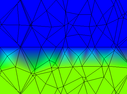
Bleed from continuous property across the boundary click to enlarge
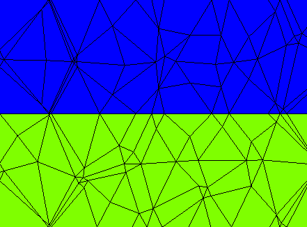
A discontinuous property click to enlarge
Schematic image illustrating node duplication at compartment boundaries (horizons, faults and mesh boundaries) when the Allow discontinuous properties option is used. Note that the image shows artificial gaps but in reality nodes in the mesh will not change position. click to enlarge
Split along selected surfaces Select this option if you want to model slipping ('moving') surfaces with a geomechanical simulator. This will enable the 'Surfaces table' on the form where you can select the surfaces you want to split. Only select those surfaces that you are actually going to simulate as slipping surfaces, because any extra 'split surface' will complicate the simulation. Some important remarks:
Select the surfaces you want to split in the Surfaces table on the form.
You can create a property with split node classes to visualize the side of the surface where the node (or element) is located (side 1, side 2 or shared). This way you can QC the split, or use the property in further calculations with the Property Calculator.
To create the property, right-mouse click on the surface in the JewelExplorer to open its context menu and choose Create > Create Node Side Property From Surface (to create a node side property) or Create > Create Element Side Property From Surface (to create an element side property). The property is added to the Properties folder of the 3D Mesh.
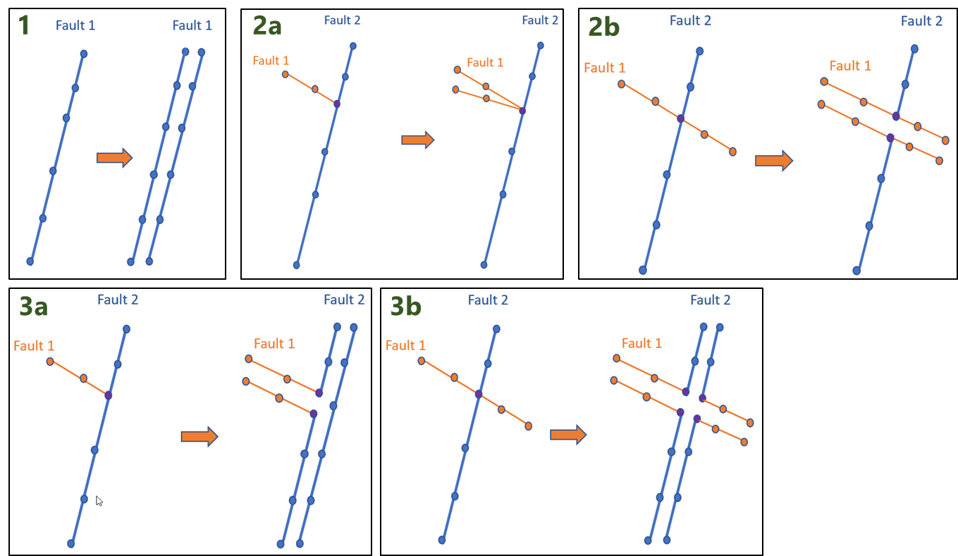
Schematic image illustrating split surfaces ending at, or intersecting other surfaces when the 'Split along selected surfaces' option is used. This example shows faults, but the rules apply to all types of surfaces (faults, horizons, unconformities and intrusions). Image 1: Split surface. Image 2a: When a split surface ends at another surface, the split is reduced to zero at that location. Image 2b: When a split surface intersects another surface, the split continues. Image 3a: When a split surface ends at another split surface, the split is not reduced to zero but maintained (compare image 3a with 2a). Image 3b: When a split surface intersects another split surface, both splits continue. click to enlarge
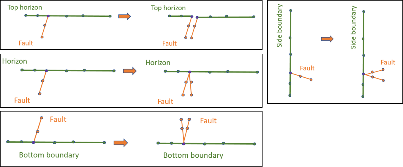
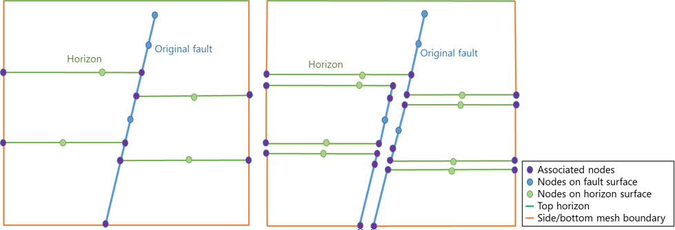
Schematic image illustrating split surfaces ending at mesh boundaries. This example shows faults, but the rules apply to all types of surfaces (faults, horizons, unconformities and intrusions). When a split surface ends at the top surface (upper left image), it maintains its split. When a split surface ends at a mesh boundary (side or bottom) or at another surface, the split is reduced to zero at that location. click to enlarge
You now have a 3D volume mesh suitable for use with various geomechanical Finite Element analysis simulators.
If you are going to create the geomechanical model, you can do so with the model > Geomechanics > Modeling workflow, see The geomechanical modeling workflow .
If you are going to use Abaqus, you can create an Abaqus case in the Abaqus workflow in the simulate strip, see Create Case.