Creating the mesh boundaries
For finite element analysis, you must have a (3D mesh) model within a fully-enclosed volume. In the Create Boundary step in the workflow, you define this volume. Based on this volume, mesh boundaries are created and stored, as tri-meshes, in the JewelExplorer. Depending on the data source selected in the previous step, Assign Data, the options that are available on the Create Boundary form differ.
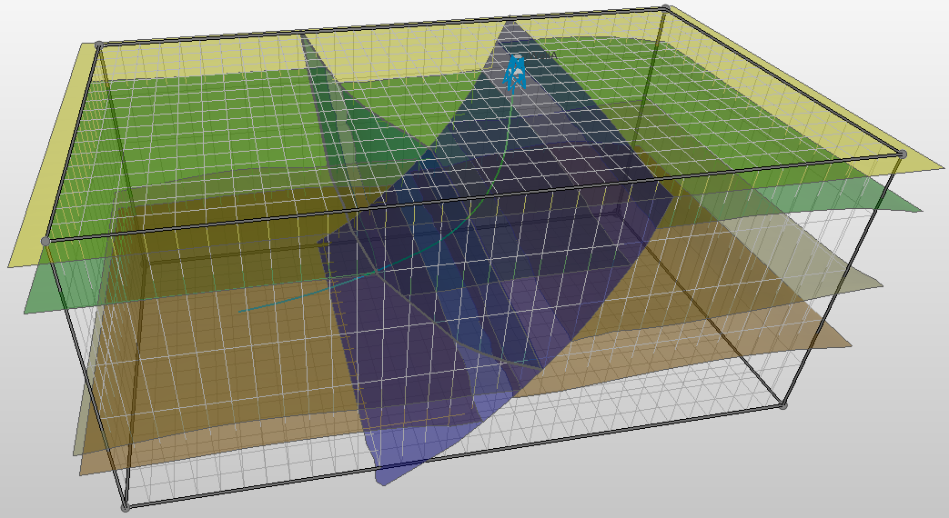
3D mesh structural model with an area box to define the mesh boundaries. The lateral dimensions of the area must be (slightly) smaller than the structural model. click to enlarge
Creating the mesh boundaries:
- If you do not already have the form open, open the Create Boundary form (model > 3D Mesh > Create Boundary). Make sure the 3D mesh structural model you are working on is selected in the Model drop-down list.
- If you already have an area you want to use for your mesh boundaries, select it from the Area drop-down list. The side and bottom faces of the area box will define the vertical and bottom mesh boundaries (the shallowest horizon will form the top of the enclosed volume). To avoid any issues in creating proper connections at the boundaries, the lateral dimensions of the area must be (at least slightly) smaller than the dimensions of the surfaces assigned to your model. If you do not have a suitable area to select, you can create one using the Area Tool (Shift +F6). See Creating an area with the Area Tool.
- In the boundaries section, the available options depend on the data source that was used in the Assign Data step. When you have assigned surfaces from a structural model, you can only use the Create New option. When you have assigned surfaces from a surface set to your 3D mesh structural model, there are two options active on the form: Create New and Use Existing.
- Create New - default option. Uses the assigned area to define your mesh boundaries. Five mesh boundary surfaces (saved as tri-mesh surfaces in the Mesh Boundaries folder in the JewelExplorer) will be created using the edges of the area box: the vertical faces and the bottom. Together with the shallowest horizon that is assigned to your 3D mesh structural model that is 100% within the selected area, they define the volume of your model.
- Use existing - only available if you have selected surface sets in the Assign Data step. From the Source drop-down list, select the folder that contains the mesh boundary surfaces that you want to use. This can be either Imports or Data. The selection you make here populates the table below. In the table, select the mesh boundaries that you want to use by checking the check boxes.
- Click OK to cut the horizon surfaces of the 3D mesh structural model to the size of the area, and create the five mesh boundaries: four vertical and one bottom mesh boundary (the uppermost surface horizon will form the top surface of the enclosed volume). The boundaries will be available in the JewelExplorer, in the Mesh Boundaries folder under the 3D mesh structural model.
For more information about boundaries, see Boundaries and Feature Sets.
When the boundaries have been created, the Set Element Sizes form will open as the next step in the Surface Meshing workflow.
Sometimes the mesh boundaries are not all created correctly. This can be the result when the Area is too large, or when there is a free edge in a surfaces at the intersection with the mesh boundary. It is recommended to fix this in the original model and then redo the creation of Mesh boundaries.
To support legacy models or step outs, you can assign a model directly from surface sets. In that case, mesh boundaries that are in the Imports or Data folder can be assigned on the form as the new mesh boundaries. JewelSuite then still needs an area for validation purposes later in the workflow. You have to ensure that the assigned surfaces, the mesh boundaries and Area are fully consistent for the next steps to work properly.
Creating an area with the Area Tool
Open the Area Tool (Tools > Area Tool from the Workspace section on the right of the Strip, or Shift + F6), then click Autofill Parameters at the bottom of the form.
On the Autofill Parameters form that appears, select the structural model or surface set you assigned to the model and click OK. This will create the area.
The area will appear in your 3D View and is stored in the JewelExplorer. It is important that the area is at least slightly smaller than the enclosed surfaces.
To move the area box, click an edge of the box, hold down the Shift key on your keyboard and drag to move the entire box. To resize, click an edge and hold down the Ctrl key instead while you drag. You can also click on the corners (which turn yellow) and drag while holding the Shift or Ctrl key down.