Visualizing split nodes
When you have split the nodes of the surfaces in your 3D mesh using the Mesh Options form, you can create a QC 3D mesh with the Visualize split nodes form (model > 3D Mesh > Tools > QC). On the QC grid, each split surface is automatically shown as a gap, which makes visual QC of the split surfaces easy. The QC 3D mesh will be stored under the 3D Meshes folder in the JewelExplorer. This QC 3D mesh model will carry its own symbol (![]() ) and can only be used for visual QC purposes.
) and can only be used for visual QC purposes.
To create a QC Mesh
- Select the 3D mesh of interest from the Model drop-down list.
- Set the gap size. This is the magnitude by which the QC grid will show the gap at each spit surface. By default a gap size of 10 m is used.
- Click OK to create the QC Mesh and close the form.
Now that you have a QC mesh model, there are several ways to do the visual QC:
- Open a new 3D View (Workspace > Views > 3D View or Alt+F1).
- In the JewelExplorer, select the full volume of the QC Mesh of interest.
- In the toolbar of the 3D View, select the View from Top option
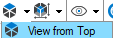 .
. - Inspect the gap in each split surface.
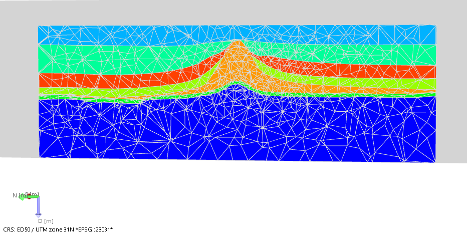
Inspect split nodes using a top view in the 3D View. click to enlarge
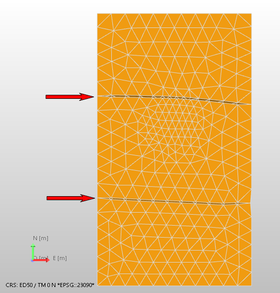
- Open a new 3D View (Workspace > Views > 3D View or Alt+F1).
- In the JewelExplorer, select the split surface(s) from the QC mesh model you want to inspect.
- Inspect the split surface(s).
Inspect split nodes in the 3D View. Top image is the original surface, bottom image is the same surface with split nodes in the QC mesh. click to enlarge
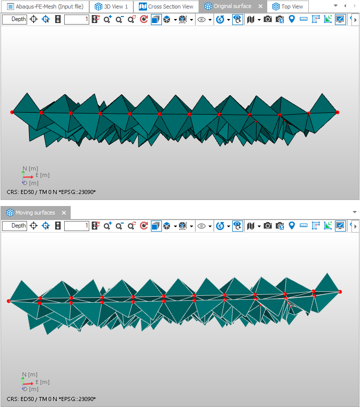
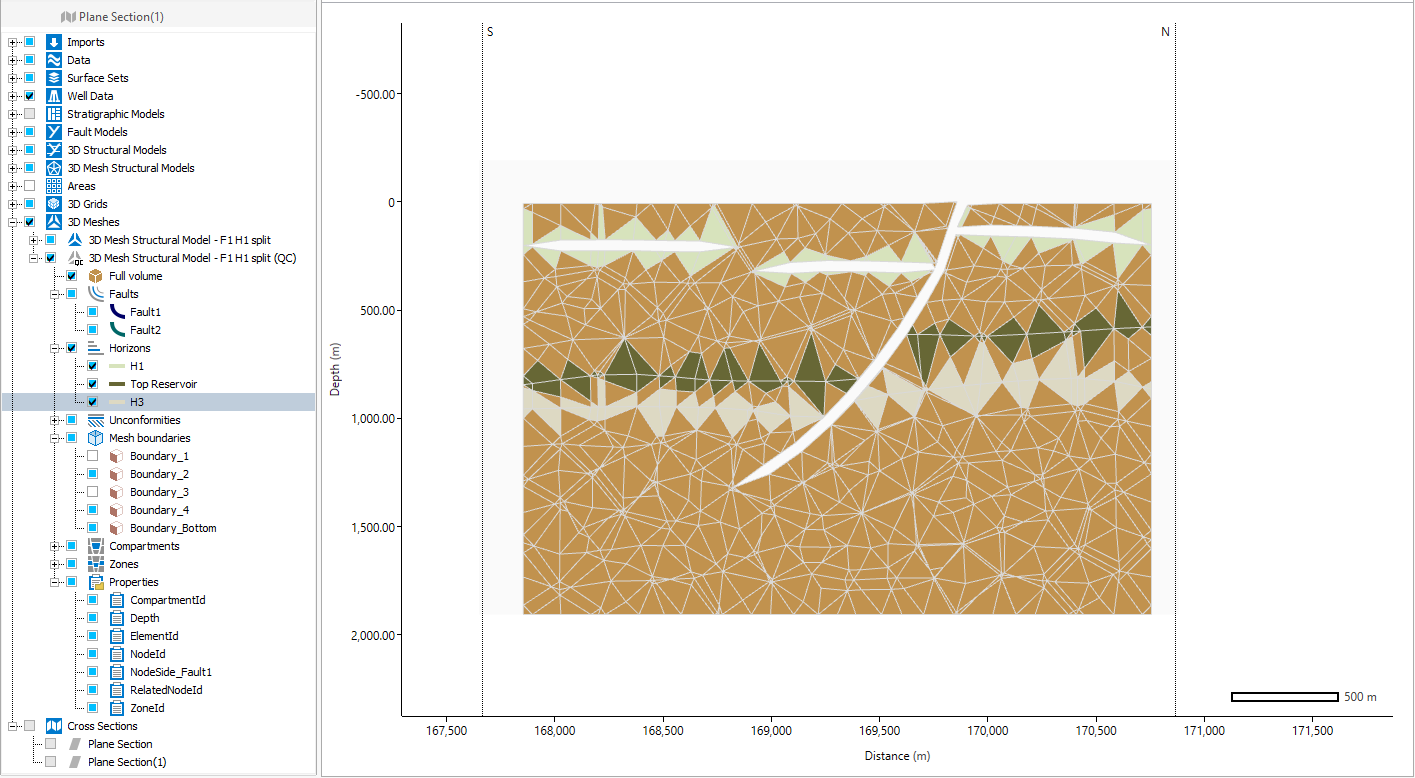
Fault in the QC grid displayed with the 'NodeSide' property selected, for easy identification of the node side (where split). click to enlarge
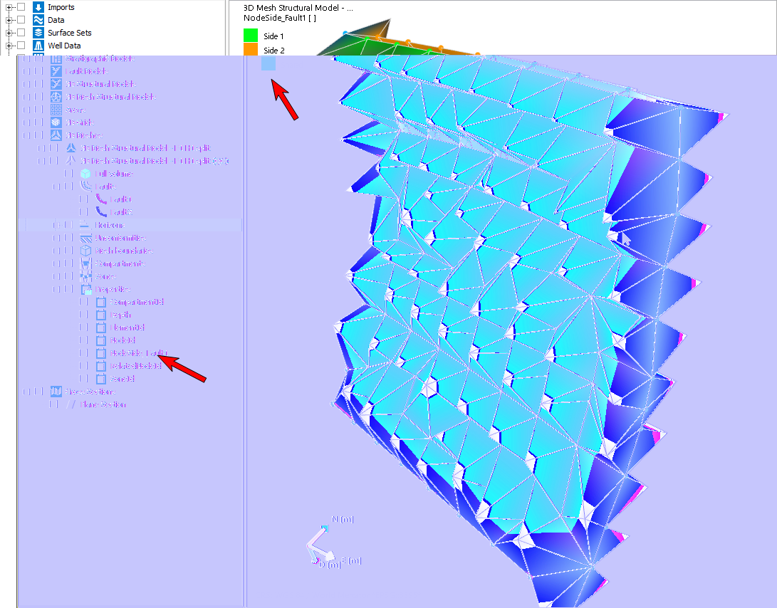
- Open a new 3D View (Workspace > Views > 3D View or Alt+F1).
- In the JewelExplorer, select the full volume of the QC Mesh of interest.
- Create a Planar Section perpendicular to the fault(s) of interest, using the toolbar of the 3D View (
 and then
  ).
). - Right- mouse click on the plane section in the JewelExplorer to open the context menu.
- Select Use as a clipping pane. This will hide part of the volume and enable you to look 'inside' your model.
- Keep both Shift and the left-mouse button pressed to make the plane section selectable for movement.
- Click in the plane section and move the mouse to slide through the model and inspect the split nodes.
- Right-mouse click on the plane section in the JewelExplorer to open the context menu.
- Select Show cross section view. This will open a new Cross Section View, which you can use for QC-ing the split fault(s) as well.
- The Cross Section View is linked to the location of the plane section in the 3D View. When you move the plane section in your 3D View, the Cross Section View is updated as well.
- Right-mouse click on the Plane section in the JewelExplorer and select 'Show cross section view' on the context menu. This opens the Cross Section View with the section displayed.
- You can visualize any other object in the Cross Section View that is highlighted in blue in the JewelExplorer.
Next follow two examples for visualizing the cross section:
With clipping pane
Inspect split nodes using a plane section in the 3D View. click to enlarge
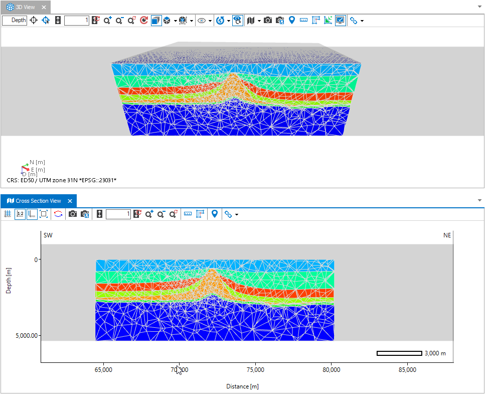
Inspect split nodes using a plane section in the 3D View and a Cross Section View. click to enlarge
Directly in cross section view
Inspect split nodes using a plane section in the 3D View and a Cross Section View. click to enlarge
If you notice anything unexpected during the visual QC, you can create a new mesh using the Split along selected faults option, with another selection of faults and perform another visual QC.
If you are going to use Abaqus for geomechanical FE analysis, you can create an Abaqus case in the Abaqus workflow in the simulate strip, see Create Abaqus case.