Editing fault cutoff lines
Fault cutoff lines are the locations where the faults intersect with the horizons in your structural model. With the Fault Cutoff Line Edits form (Model > 3D Structure > Fault Cutoff Lines) you calculate these lines that can be inspected and optionally edited. The position of these lines, pre-editing, are determined by the horizon input data, the horizon construction settings (proportional/conform) and the hierarchical relationships with other horizons. You can manually edit these lines, as such influencing the location of the horizon-fault intersection, after which the horizon surfaces will be reconstructed (taking along the edits) by clicking Apply or OK at the base of the form. This functionality can be important for structurally complex reservoirs where juxtaposition along the faults is a crucial factor.
When fault cutoff lines (or its control line or control node, see further below) are edited, the edited nodes are treated as 'extra’ input data points, next to the horizon input data. This means that the gridder algorithm, which handles the surface construction, will take these updated node positions into account, but does not treat these edits as more 'important' than the horizon input data. In other words, horizon input data and fault cutoff line edits are treated as 'equally important' by the gridder. This is important to realize in case the horizon input data and edited fault cutoff lines get 'in conflict'. Under normal circumstances the fault cutoff line edits are honored, which means the constructed horizon surface will intersect the fault at the updated/edited fault cutoff line position. However, when fault cutoff line edits are too extensive in relation to the horizon clean-up distance, the gridder cannot honor the horizon data as well as the fault cutoff line edits (the resulting surface would be too much bent/curved, image 1B below). The gridder will alternatively construct a smooth surface, trying to honor all input data, but not succeeding in this. The resulting surface will therefore not intersect the fault exactly at the fault cutoff line position(s) that you created (image 1C below). It is therefore recommended to keep any fault cutoff line edits proportional to the clean-up distance of the respective horizon (image 2B below).
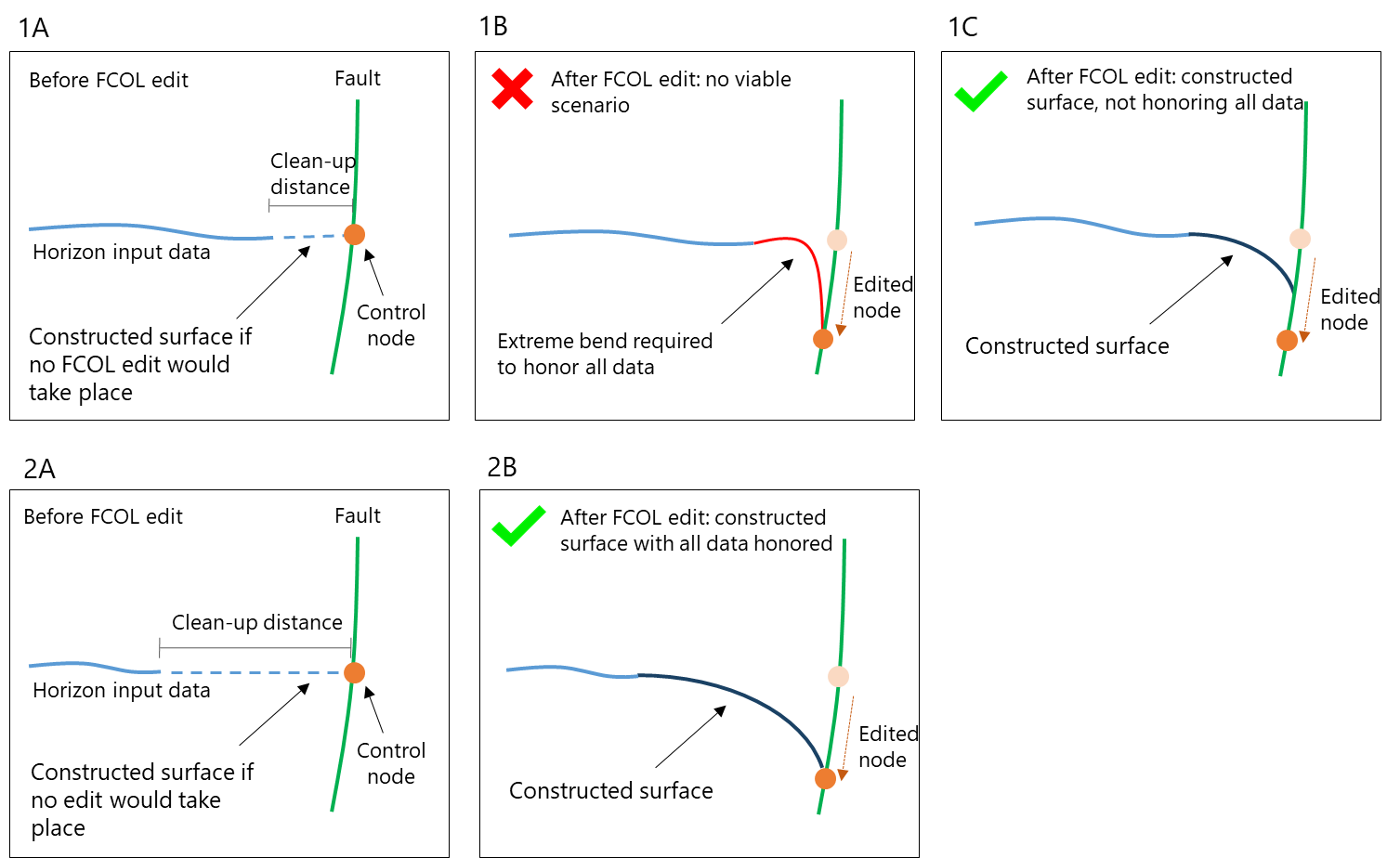
The importance of clean-up distance illustrated by schematic examples. Images 1A, B, C show how a small clean-up distance, relative to the fault cutoff line edit, results in a constructed surface not honoring the fault cutoff line edit (1C). Images 2A, B show how a greater clean-up distance enables the gridder to honor all input data, while constructing a smooth surface. click to enlarge
Inspection and editing of fault cutoff lines can be done in the 3D View or in the dedicated Solve Fault Cutoff Lines 3D View, which opens simultaneously with the form. Once you are done with inspecting and editing and click Apply or OK at the base of the form, the horizon surfaces are (re)constructed, using the edits you made.
The Fault Cutoff Line Edits form can be opened in two ways:
- Automatically when you clicked OK on the preceding Construct Surfaces form (If you don't want to edit the fault cutoff lines, click Cancel on the Fault Cutoff Line Edits form).
- By clicking the Fault Cutoff Line Edits button in the Structural Modeling workflow (model > 3D Structure).
In case you want to stop the process during the calculation of the fault cutoff lines, after clicking Apply or OK on the form, you can use the Cancel button in the bar at the base of the application window.

Cancel the calculation of fault cutoff lines. click to enlarge
You can adjust the line width, the marker diameter and the marker border width of a fault cutoff line using the Display settings form (on that form, go to Objects > Intersections > Fault cutoff).
Hierarchical concept in fault cutoff lines
The same hierarchical principle that is valid for the construction of horizon surfaces (i.e. surfaces with geometric priority are constructed before surfaces with lower geometric priority, see The building sequence), applies to fault cutoff lines. As the geometry of the marker-based surface is 'steered' by the surfaces with geometric priority, this means that any edit (or 'lock') of fault cutoff lines of surfaces with geometric priority can potentially influence the geometry of surfaces that are constructed later, e.g. marker-based surfaces. If you do not want this, you can lock the fault cutoff line to fix its position in space. However, as explained above, it depends on the clean-up distance of the respective surface, the construction settings (proportional/conform) and the hierarchical relationships with other horizons, whether or not the 'lock' can be honored by the gridder.
Calculating the fault cutoff lines
- Open the form. This can be done in two ways: automatically after you clicked OK on the preceding Construct Surfaces form, or by clicking the Fault Cutoff Line Edits button in the strip. If you use the last option, make sure you have performed the Construct Surfaces step (previous step of the Structural Modeling workflow). The dedicated 'Solve Fault Cutoff Lines 3D View' opens simultaneously with the form.
- Under Model, select the Structural Model for which you want to edit the intersections. Upon selection:
- The left table on the form shows all the horizons or faults in the selected Structural Model (whether horizons or faults are shown depends on the selection under 'Group fault cutoff line edits by').
- The right table shows the following:
- If you did not calculate the fault cutoff lines with the Construct Surfaces form, the right table will be empty. In that case, continue with step 3 below.
- If you already calculated the fault cutoff lines with the Construct Surfaces form, the right table will show the horizon-fault combinations in the selected stratigraphic level of your structural model. In that case, continue with step 6 below.
- Under Stratigraphic level, select the level of your stratigraphic model that contains the surfaces for which you want to calculate and edit fault cutoff lines. You can optionally check the box Do not calculate fault cutoff line edits for surfaces based on markers. This option allows you to exclude the surfaces which are based on markers. It is recommended to use this option when you plan to perform fault cutoff line edits on other surfaces than marker-based surfaces. The reason is that marker-based surfaces are constructed 'last' (see The building sequence) and are aligned conform/proportional to surfaces with geometric priority. This means that any edits on fault cutoff lines of surfaces with geometric priority would potentially influence marker-based surfaces, and it is recommended to QC the effect of those edits on the marker-based surfaces first.
- Click the Calculate button
 on the form to start the calculation of the horizon-fault intersections of the surfaces at the selected stratigraphic level.
 -
When fault cutoff lines are calculated:
- The right table is filled with all the calculated fault cutoff lines.
- In the JewelExplorer, the calculated fault cutoff lines are added to (folders within) the newly created 'Fault Cutoff Line Edits' folder under the corresponding Structural Model.
- The 'Solve Fault Cutoff Lines 3D View' shows the horizon-fault combination that is at the top of the right table on the form (it is auto-selected). Click any other horizon-fault combination, to show it in the view.
Displaying fault cutoff lines in the dedicated 'Solve Fault Cutoff Lines 3D View'
Before you start editing fault cutoff lines, read this section to learn how to control their visualization in the dedicated 'Solve Fault Cutoff Lines 3D View'. You can control their visualization by:
- the Fault Cutoff Line Edits form
- the JewelExplorer
To use the JewelExplorer, first locate the fault cutoff lines under the 3D Structural Model > Fault Cutoff Line Edits folder. Here, you find the calculated fault cutoff lines grouped (in folders), initially by horizon name (default setting). You can, however, group them differently, or not at all. To do this, open the context menu of the 'Fault Cutoff Line Edits' folder and select your preferred grouping option (see image below). Once located, you can check the box for each fault cutoff line to visualize it in the 'Solve Fault Cutoff Lines 3D View'.
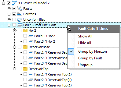
Organize your fault cutoff lines in the 'Fault Cutoff Lines' folder by using its context menu. click to enlarge
The primary method of visualizing fault cutoff lines, however, is through the Fault Cutoff Line Edits form. On the form, use the two tables to filter and select the fault cutoff lines to be displayed in the 'Solve Fault Cutoff Lines 3D View'. Additional display options are also available, and detailed in the steps below.
- Depending on your model, you may be presented with a large list of fault cutoff lines in the right table of the form. To aid in selecting the fault cutoff lines that are of interest to you, a filtering function is available and is controlled in the left table. This filtering function allows you to filter the list of fault cutoff lines by horizon or fault, using the Group fault cutoff line edits by option (note; this includes all fault cutoff lines, not only the 'edited' fault cutoff lines). To filter for a particular horizon or fault, first select the Horizon or Fault option. Find the horizon or fault and check its associated box in the Filter column. This will refresh the list of fault cutoff lines in the right table based on your selection. You can select multiple horizons or faults to filter on.
- When you group by Horizon, the left table automatically lists all the horizons, even if they do not contain an intersection with a fault. By filtering per horizon, you can easily see the intersections specific to the selected horizon.
- When you group by Fault, the left table lists only the faults which have an intersection with a horizon. See step 5 below for recommended view settings when filtering by faults.
- To display a fault cutoff line in the view, select (click on) a fault cutoff line in the right table. To display multiple fault cutoff lines, use Ctrl or Shift while clicking. The dedicated 'Solve Fault Cutoff Lines 3D View' responds to the selection, displaying the horizon, the fault (in transparent mode) and all the fault cutoff lines for that fault. The displayed objects are also automatically activated (checked) in the JewelExplorer (n the structural model folder): uncheck the objects that you don't want displayed in the dedicated view.
-
In the View Settings section on the form, select whether you want to display the Hanging Wall, Footwall or Both fault cutoff lines.
If you have created (by zooming, rotating and selecting) a visualization in the 'Solve fault cutoff lines 3D View' and you want to add more fault cutoff lines to that same view, add them by selecting them in the JewelExplorer. This prevents the automatic resetting of the view. - You can choose to set the option Display related fault-fault intersections. This will render the intersections of other faults onto the displayed fault plane and helps you understand the truncations in the fault cutoff lines. Also, it provides a visual aid on the different fault blocks to prevent you from moving a control node of a fault cutoff line accidentally into another fault block when you are editing your fault cutoff lines (see Editing fault cutoff lines). The visibility of the intersections is also coupled to the view settings of the fault cutoff lines as described in the previous section.
- Under Horizons, you can select whether to display the constructed surface (select Constructed) or original input horizon (select Input). The original input horizon is the horizon as it exists in the selected 'Source' on the Assign Data form. You can also select None to completely hide the horizon and have the fault (and associated fault cutoff lines) in full view.
Once you have displayed the relevant fault cutoff lines in the 'Solve Fault Cutoff Lines 3D View', you can begin with manually editing them using the Editing Tools on the floating palette (see Editing fault cutoff lines). To open the Editing Tools, you can either use the button ![]() on the form, Shift + F1 or the Editing Tools option from the Views drop-down menu. (Note that nodes on the fault cutoff lines only become visible after you selected one of the editing tools.) When you have finished editing, return to the Fault Cutoff Lines form and click Apply or OK to reconstruct the surfaces. For more info see Visual QC of (re)constructed surfaces.
on the form, Shift + F1 or the Editing Tools option from the Views drop-down menu. (Note that nodes on the fault cutoff lines only become visible after you selected one of the editing tools.) When you have finished editing, return to the Fault Cutoff Lines form and click Apply or OK to reconstruct the surfaces. For more info see Visual QC of (re)constructed surfaces.
Recommended practices for visualizing and editing fault cutoff lines
When filtering for horizons
Visualizing fault cutoff lines related to a particular horizon:
- Select Horizon under 'Group fault cutoff lines by' (located above the left table).
- Check the box for each of the horizons of interest.
- Select one fault cutoff line from the list in the right table, set the desired view settings and edit the cutoff lines using the editing tools.
- Proceed one by one until you have edited all of the fault cutoff lines of interest.
When filtering for faults
Visualizing faults is easiest when you use a combination of the Fault filter and Horizons set to 'None'. This allows you to better view the fault cutoff lines along the fault of interest.
- In the left table, select Fault under 'Group fault cutoff lines by'.
- Check the box for each of the faults of interest.
- Under Horizons, select None (base of the form).
- Select the fault cutoff lines of interest in the right table.
- Edit the cutoff lines using the editing tools.
Using context menus to display connected faults and horizons
When you are editing the fault cutoff lines for a specific fault, it can be very helpful to quickly display all the horizons that this fault has an intersection with. Also, when you are editing intersections of a specific horizon, you might want to quickly display all faults that this horizon has an intersection with. Open the context menu by right clicking on the tri-mesh of the relevant fault or horizon in the JewelExplorer, and choose Show connected surfaces. You can also open the context menu by right-clicking on the object in the view you are working in.
Similarly, you can show all surfaces that are related to a specific fault cutoff line. Open the fault cutoff line's context menu by right-clicking on the intersection in the JewelExplorer, and choose Show related surfaces. You can also open the context menu by right clicking on the intersection in the view you are working in.
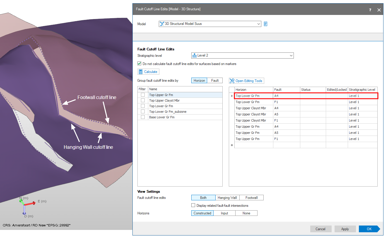
Example of a horizon-fault intersection in the dedicated 'Solve Fault Cutoff Lines 3D View'. The visualization is controlled by selections you make in the table (right-hand side) of the Fault Cutoff Line Edits form (in this example Horizon 'Top Lower Gr FM' - Fault 'A4'). click to enlarge