Assigning a Training Image
With the Assign TI (Training Image) form of the Facies Modeling workflow (model > Facies > Assign TI) you can assign a training image to a Volume of Interest (VOI). This workflow step is only relevant if you are using Multi Point Statistics (MPS) as modeling method. For more information on MPS, see Multiple-Points Statistics (MPS).
A training image is a two- or three-dimensional facies property from which MPS can extract the statistics of depositional patterns for stochastic reproduction. Although the word 'image' triggers an association with a picture or photograph, the more correct term would be 'training volume', which can also be two-dimensional. In JewelSuite Subsurface Modeling such a training image is a facies property on an EasyGrid. For efficient working with different training images, you can have multiple facies properties on one EasyGrid.
- Minimum requirements for a 3D training image: 25 x 25 x 14 cells (in I, J and K direction).
- Minimum requirements for a 2D training image: 25 x 25 cells (in I and J direction).
In the JewelExplorer, you need to have a training image grid available in order to select it on the form. There are multiple ways of creating a training image:
- You can load a training image from Training Image Library included with the application, see Training Image (TI) Library.
- You can use the editing tools to draw a training image using the editing tools, see Example - Creating a training image using editing tools.
- You can import a training image that you have created outside JewelSuite Subsurface Modeling.
MPS employs a 'search template' to scan the training image in order to obtain the statics of the depositional facies patterns, the conditional probabilities of having a facies appearing in certain spatial configuration. In other words, MPS learns from the training image how to produce stochastic realizations of the facies patterns. This should not be confused with clone-stamping as known from image manipulation software.
Rules of thumb for a training image
- MPS is a pixel-based algorithm and reproduces patterns based on the number of pixels; actual dimensions don't exist in the training image. One cell (pixel) in the training image corresponds to one cell in model grid. You can have different grid cell size in the training image and model grid, however for your own convenience it can be advantageous to align the dimensions, so that for example a 50m wide channel appears to be 50m wide in the training image.
- In all cases you need to make sure that the facies codes (which consists of a 'Name' and 'ID') in the facies property of your training image match the facies codes of your upscaled grid properties. If your upscaled grid property contain facies code 'Name = SaND / ID = 2', and you want the sand in your training image to correspond to this facies, then the sand in your training image has to be named 'SaND' (case sensitive) and also have ID = 2. You can change the names and ID's of facies using the context menus of the upscaled property and/or the training image property (in the JewelExplorer, go to the upscaled property and/or the training image property, open the context menu and choose Properties > Edit classes). You can also change the facies code with the Property Calculator.
- You can have extra facies classes in your training image which do not occur in your upscaled grid property. This way, you can introduce 'extra' facies into your model via the training image.
- You should avoid situations where you have more facies classes in your upscaled grid property, than in your training image. The modeling algorithm will be able to run, but the 'extra' facies class(es) will not appear in the modeling result away from the cells with the upscaled property. A warning pops-up on your screen.
- The training image should be large enough to capture multiple repetitions of the geological phenomena.
- The training image does not have to be stationary (without a trend). In case the training image contains a trend, you need to create an auxiliary trend property within the training image grid, describing the trend. Furthermore you need to have a trend property on the model grid, describing the same trend. Both trend properties can be linked using the Trends and Proportions form, which is the next step of the workflow.
- You can simulate a 3D grid with a 2D or a 3D training image, but since a 2D training image does not contain information about vertical facies patterns, these will not be contained in the result. For 2D model grids you have to use 2D training images.
- JewelSuite Subsurface Modeling applies a search template. An optimal size of the search template is automatically determined and used.
To assign a training image
- Under Model, select the facies model to which you want to assign the training image.
- From the Volume of Interest table, select the Volume of Interest with MPS as modeling method. Upon selection, the right side of the form updates with the options related to MPS.
- From the Training image grid drop-down list, select the grid that contains your training image, then select your training image from the Training image property drop-down list. Upon selection, the tables on the form fill with the names and ID's of the facies as defined in the training image (right-hand table) and upscaled grid property (left-hand table).
- Minimum requirements for a 3D training image: 25 x 25 x 14 cells (in I, J and K direction).
- Minimum requirements for a 2D training image: 25 x 25 cells (in I and J direction).
- Review both tables: each facies that appears in the upscaled property and in the training image must have the same combination of 'Name' and 'ID' in both tables, see point 2 under 'Rules of thumb for a training image' above.
- Limit extent of TI If you check the box, you can use the I/J/K sliders to crop the extent of the training image.
- Minimum requirements for a 3D training image: 25 x 25 x 14 cells (in I, J and K direction).
- Minimum requirements for a 2D training image: 25 x 25 cells (in I and J direction).
- Scaling Factors If you check the box, you can set a scaling factor to use for I/J/K directions. Upon activating this option, all three sliders can be adjusted. Depending on the value you select, the patterns of the training image are reproduced coarser or finer in your grid.
- Click Apply and keep the form open, or click OK to move to the next step in the workflow, Trends and Proportions.
Example - Creating a training image using editing tools
In this section you will learn to create a training image using editing tools if you do not want to use the images from the training library.
- Create a new empty 3D grid using the Create Easy Grid form.
- On the form, create a new grid and enter the grid name in the adjacent field. Subsequently, select the model area, or create a new area or edit an existing model area using the edit button
 that opens the Area Tool.
 - In the next step, enter the vertical dimensions of the training image grid. For a 2D training image, enter # of K-layers equal to 1.
- Minimum requirements for a 3D training image: 25 x 25 x 14 cells (in I, J and K direction).
- Minimum requirements for a 2D training image: 25 x 25 cells (in I and J direction).
- Click Create and you can access the new grid in the JewelExplorer under the 3D grids folder.
Important If the following minimum requirements are not met, sampling of the training image is not possible and you cannot use MPS as a modeling method: - On the form, create a new grid and enter the grid name in the adjacent field. Subsequently, select the model area, or create a new area or edit an existing model area using the edit button
- Create a new facies property that you will use to draw the training image. To do this, use the context menu of the Properties folder of the newly created 3D grid, and select Create Property to open the Property Calculator.
- In the property calculator, create a new target property and select Facies as Property Type. Select a Folder location for the property.
- In the Expressionfield of property calculator, enter ‘0’ and click OKat the bottom of the property calculator tool. This will create a facies property with all grid cells having zero value.
- In this step, you are going to add classes to the new facies property and also change the facies class colors. In the JewelExplorer, use the context menu of the new facies property and select Properties and then Edit Classes. On the Discrete Property Class Editor form, define the facies types (e.g. shale, sand, clay, etc) that you will use in the training image. Refer to the rules of thumb (2, 3 and 4) above for defining facies classes.
- In the last step, use the Property Editing Tools (Workspace > Tools) to draw the training image.
- Select the new 3D grid in JewelExplorer and open the editing tool. Select the pencil icon in the Property Tools section, and under settings select the newly created facies property from the drop down.
- The overlapping squares represented by the facies class colors indicate the foreground and background colors for drawing. Hold Ctrl + left click to draw a continuous curve with the foreground color, or hold Ctrl + right click to draw with the background color. In the example below, the image is drawn with the foreground color (yellow) representing Sand.
- Adjust the width and thickness values of the curves at the bottom of the editing tool.
- You can also draw a 3D training image using the same workflow as listed above with some variations. For example, you can
- Create the easy grid with more than 14 K-layers.
- While drawing the facies, use a higher thickness value for layers on the editing tools. To add vertical variation of facies, specify the set of K-layers while drawing on the model grid.
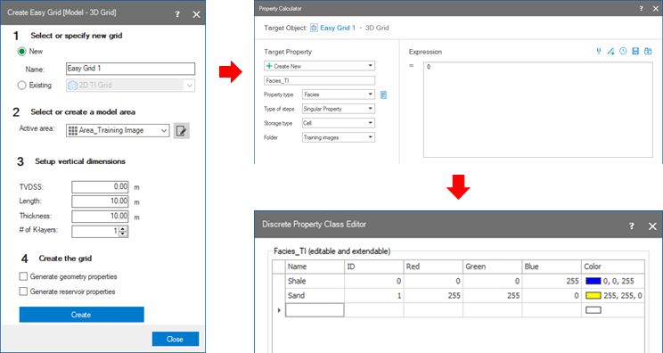
Workflow steps from 1 to 3: Create an easy grid; create facies property using property calculator; define facies classes for the training image. click to enlarge
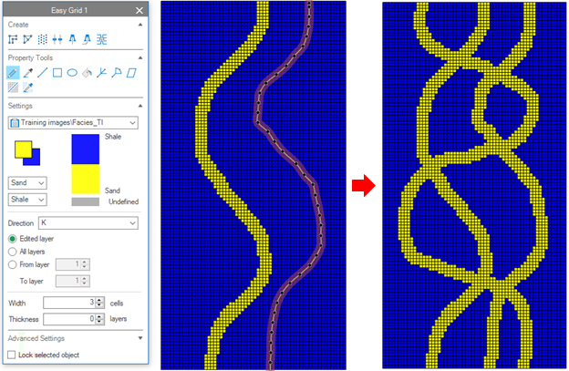
Use the Editing tool to draw the facies on the grid model. click to enlarge