Applying trends and facies proportions
With the Trends & Proportions form (model > Facies > Trends & Proportions) you can enforce the modeling algorithm to use a specific facies proportion based on a Vertical Proportion Curve (VPC), a lateral trend or a 3D trend. Based on the modeling method of the selected Volume of Interest (VOI), different control tabs are available on the form (see image below for the tabs per modeling method).
When you are using modeling method MPS, you can link a trend property of your training image grid with a trend property of your model grid (i.e. the grid that holds the Volume of Interest). Linking the depositional trend of a training image requires the training facies property to represent a trend, and a continuous property on the training image grid to capture such trend. For instance, if you have proximal to distal trend in the training image in N-S direction, you need to create a continuous property with a trend in N-S direction. To link the depositional trend of the training image to the modeling grid (VOI), you need to create a continuous trend property on this grid as well.
Depending on the modeling method of the selected Volume of Interest, the Transform & Trends form shows different control tabs. click to enlarge
Facies proportions (lower part of the form)
The 'Facies Proportions' section at the lower part of the form is always visible, irrespective of the modeling method of the selected Volume of Interest. The table in that section is filled based on the data that you enter in the various tabs at the upper part of the form (and which are modeling method dependent) and the settings provided in previous steps in the workflow.
Target based on This selection defines the source that will be used to set the input proportions to use in the modeling run; the modeling algorithm tries to reach these input proportions while populating the grid with facies. Not all options are always available and depend on your selections at the top of the form (i.e. whether you are incorporating a trend, or selected 'None'). Select whether your target is based on the 'Upscaled data', 'Training Image', 'Manual Input' or a 'Vertical, Lateral or 3D Trend'
- Upscaled When you select this option, the table is for information only. The facies proportions are based on the upscaled proportions.
- Training Image When you select this option, the table is for information only. The facies proportions are based on the proportions in the training image and are automatically filled in form you in the 'Target' column.
- Manual Input When you select the Manual Input tab, the 'Target' column in the table becomes editable and you can type the proportion for each facies.
- Vertical, Lateral or 3D When you select this option, the table is for information only. The facies proportions are based on the proportions you set on the Vertical, Lateral or 3D tab, and automatically filled in, in the 'Target' column.
Table columns
ID For information only. The ID number refers to a facies.
Raw For information only. This column shows the facies proportions as they occur in the raw facies logs.
Upscaled For information only. This column shows the proportions as they occur in the upscaled grid property.
TI For information only. This column shows the proportions as they occur in the training image.
Trend For information only. This column shows the proportions as set on the Vertical, Lateral or 3D tab.
Target The facies proportions that the modeling algorithm tries to reach. When you type the values manually, make sure the proportions sum up to 100%. When using the facies proportions in an uncertainty study, it is highly recommended to define at least two proportions as uncertain. This will ensure that the non-uncertain proportions will keep their (fixed) value, instead of being normalized (to enforce that the sum of all values is 100%) when the facies proportions are sampled in an uncertainty study.
 next to each Target entry field to open the Uncertainty Parameter dialog. For how to use the controls on the dialog, see The Uncertainty Parameter dialog. For information about parametric uncertainties and how to use them in JewelSuite Subsurface Modeling, see Incorporating uncertainty in static or dynamic modeling.
Vertical, Lateral or 3D
You can enforce the modeling algorithm to use a specific facies proportion based on a VPC, a lateral trend or a 3D trend.
None The facies proportions used are defined in the 'Facies Proportions' section at the base of the form, where you can choose the facies proportions to be from 'Upscaled' or 'Manual Input'.
Vertical proportion curve & lateral This selection enables the following checkboxes:
Vertical From the drop-down list select which property you want to use:
- From upscaled property the proportions of the upscaled property that you have selected in the Create Model step are used.
- Target proportions for modeling you can open a dedicated VPC form where you can assign target proportions for each k-layer in your VOI, see Assigning a Vertical Proportion Curve.
Lateral When you select this option, the table below is activated where you can select a secondary property, defined on a 2D grid or on a Facies Trend Map. When you select a Facies Trend Map, per facies the normalized property is auto-selected in the table; when you select a 2D grid you have to select, per facies, a property in the table. The drop-down lists all the properties that you can use as a secondary property.
Ensure all values in each cell sum up to 1 If you are uncertain about the proportions of the property that you have selected, check this option to ensure the Run Model step will succeed. This option will make sure that the sum of all values in each cell sum up to 1, and has the appropriate scaling.
Averaging When you combine vertical and lateral trends (i.e. when you select both the Vertical and Lateral checkboxes) you can specify the averaging method with which the facies probability for each cell is calculated. For each facies the averaging method calculates an average of the proportions from vertical (v) and lateral (l) and then normalizes these averages to add up to 1 (100%). The following averaging methods are available for selection:
- Arithmetic mean - weighted arithmetic average of v and l where the weight w is set via the slider: w * v + (1 - w) * l. This way you can ‘dim’ or ‘emphasize’ the vertical or lateral probability in your modeling result.
- Geometric mean - square root of the product of v and l: sqrt (v * l).
- Product - product of v and l: v * l. See calculation example below:
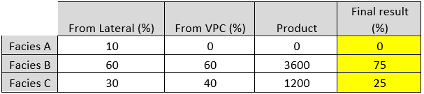
Per facies the product of lateral and vertical probability is calculated, after which the sum of all products is divided by the facies product, resulting in the (combined) probability per facies class. click to enlarge
After selecting a property for all the facies, the facies proportions used are listed in the Trend column in the 'Facies Proportions' section.
3D Selecting this option activates the table below. For each facies, select a property from the drop-down list. The properties listed are continuous properties of the selected 3D grid.
After selecting a property for all the facies, the facies proportions used are listed in the Trend column in the 'Facies Proportions' section.
Integration method Select the type of method you want to use.
Locally Varying Mean Select this option when you have enough hard data showing a clear correlation between the primary property and the secondary property.
This method uses nonstationary simple kriging with residuals from the locally varying mean probabilities and uses the values of the secondary property as the local mean in the kriging calculation. The locally varying mean approach is suitable for local mean values coming from geological interpretation. It could be used for geophysical-derived values. This option is the most correct by theory.
Bayesian Updating Select this option when you have few hard data and it is not straight forward to establish a clear correlation between the primary property and the secondary property.
This method uses the secondary property to apply a relative weight to the calculation of the facies probability. In this way, the correlation is not explicitly specified but is embedded in the local probability values. The Bayesian Updating method will give more weight to the secondary data.
Ensure all values in each cell sum up to 1 If you are uncertain about the proportions of the property that you have selected, check this option to ensure the Run Model step will succeed. This option will make sure that the sum of all values in each cell sum up to 1, and has the appropriate scaling.
Adjacent Facies tab
Use the table to determine which facies can occur next to another facies in neighboring cells. Select a facies by clicking in a row. This will activate the arrows to move a facies up or down in the table. A facies can only occur next to another facies when they are next to each other in this table. The neighboring facies are listed in the table in the 'Neighbor 1' and 'Neighbor 2' columns. This information is read only.
Click Apply to save and apply the settings you have specified and keep the form open, or click OK to save and apply the settings you have specified and move to the next step of the workflow, Control method.
Vertical, Lateral or 3D tab
You can enforce the modeling algorithm to use a specific facies proportion based on a VPC, a lateral trend or a 3D trend. If you select 'None', the facies proportions used are set in the 'Facies Proportions' section.
Vertical proportion curve & lateral This selection enables the following checkboxes:
Vertical From the drop-down list select which property you want to use:
-
From upscaled property The proportions of the upscaled property that you have selected in the Create Model step are used.
-
Target proportions for modeling You can open a dedicated VPC form where you can assign target proportions for each k-layer in your VOI, see Assigning a Vertical Proportion Curve.
Lateral When you select this option, the table below is activated where you can select a secondary property, defined on a 2D grid or on a Facies Trend Map. When you select a Facies Trend Map, per facies the normalized property is auto-selected in the table; when you select a 2D grid you have to select, per facies, a property in the table. The drop-down lists all the properties that you can use as a secondary property.
Averaging When you combine vertical and lateral trends (i.e. when you select both the Vertical and Lateral checkboxes) you can specify the averaging method with which the facies probability for each cell is calculated. For each facies the averaging method calculates an average of the proportions from vertical (v) and lateral (l) and then normalizes these averages to add up to 1 (100%). The following averaging methods are available for selection:
- Arithmetic mean - weighted arithmetic average of v and l where the weight w is set via the slider: w * v + (1 - w) * l. This way you can ‘dim’ or ‘emphasize’ the vertical or lateral probability in your modeling result.
- Geometric mean - square root of the product of v and l: sqrt (v * l).
- Product - product of v and l: v * l. See calculation example below:
Per facies the product of lateral and vertical probability is calculated, after which the sum of all products is divided by the facies product, resulting in the (combined) probability per facies class. click to enlarge
After selecting a property for all the facies, the facies proportions used are listed in the Trend column in the 'Facies Proportions' section.
3D Selecting this option activates the table below. For each facies, select a property from the drop-down list. The properties listed are continuous properties of the selected 3D grid.
After selecting a property for all the facies, the facies proportions used are listed in the Trend column in the 'Facies Proportions' section.
Ensure all values in each cell sum up to 1 If you are uncertain about the proportions of the property that you have selected, check this option to ensure the Run Model step will succeed. This option will make sure that the sum of all values in each cell sum up to 1, and has the appropriate scaling.
Depositional Patterns tab
There are two sections on the form with which you can link trends: 'Depositional Pattern Trend 1' and 'Depositional Pattern Trend 2'. Per section, the following selection options and settings apply:
Trend Property in Training Image
Grid For information only. The grid that is shown in the field is the same grid as which contains the training image that you assigned in the previous step of the workflow, Assign TI. It is auto-selected, because the trend property (which you select in the next field) needs to be a property of this grid.
Property Before you select a property, click on the green plus sign ( ). This will open a new form where you can set the azimuth of the trend. Select the property that contains the trend from the drop-down list. The property needs to be a continuous property of the training image grid. See further above how you can create a trend property.
Trend Property in VOI
Grid For information only. The grid that is shown in the field is the model grid, i.e. the grid that holds your VOI. It is auto-selected, because the trend property (which you select in the next field) needs to be a property of this grid.
Property Before you select a property, click on the green plus sign ( ). This will open a new form where you can set the azimuth of the trend. Select the property that contains the trend form the drop-down list. It needs to be a continuous property on the model grid (i.e the grid that holds your VOI). See further above how you can create a trend property.
Normalize trend properties When you check this box, both trend properties will be scaled into a range between 0 and 1.
TI facies pattern reproduction With the slider you can prioritize either reproduction of the patterns in the training image or of the trend. This way you can 'dim' (move the slider to the left) or 'emphasize' (move the slider to the right) the trend effect in your modeling result. The higher the weight factor, the more 'dominant' the trend becomes in the modeling result. When the trend weight factor is too high, the pattern reproduction quality will decrease, fully honoring the trend but ignoring the facies patterns of the training image. When the trend weight factor is too low, the modeling result will have a 'confetti' appearance. Recommended values range between 50% and 80% honoring of trend.
Vertical, Lateral or 3D tab
You can enforce the modeling algorithm to use a specific facies proportion based on a VPC, a lateral trend or a 3D trend. If you select 'None', the facies proportions used are set in the 'Facies Proportions' section.
Vertical proportion curve & lateral This selection enables the following checkboxes:
Vertical From the drop-down list select which property you want to use:
From upscaled property The proportions of the upscaled property that you have selected in the Create Model step are used.
Target proportions for modeling You can open a dedicated VPC form where you can assign target proportions for each k-layer in your VOI, see Assigning a Vertical Proportion Curve.
Lateral When you select this option, the table below is activated where you can select a secondary property, defined on a 2D grid or on a Facies Trend Map. When you select a Facies Trend Map, per facies the normalized property is auto-selected in the table; when you select a 2D grid you have to select, per facies, a property in the table. The drop-down lists all the properties that you can use as a secondary property.
Averaging When you combine vertical and lateral trends (i.e. when you select both the Vertical and Lateral checkboxes) you can specify the averaging method with which the facies probability for each cell is calculated. For each facies the averaging method calculates an average of the proportions from vertical (v) and lateral (l) and then normalizes these averages to add up to 1 (100%). The following averaging methods are available for selection:
- Arithmetic mean - weighted arithmetic average of v and l where the weight w is set via the slider: w * v + (1 - w) * l. This way you can ‘dim’ or ‘emphasize’ the vertical or lateral probability in your modeling result.
- Geometric mean - square root of the product of v and l: sqrt (v * l).
- Product - product of v and l: v * l. See calculation example below:
Per facies the product of lateral and vertical probability is calculated, after which the sum of all products is divided by the facies product, resulting in the (combined) probability per facies class. click to enlarge
After selecting a property for all the facies, the facies proportions used are listed in the Trend column in the 'Facies Proportions' section.
3D Selecting this option activates the table below. For each facies, select a property from the drop-down list. The properties listed are continuous properties of the selected 3D grid.
After selecting a property for all the facies, the facies proportions used are listed in the Trend column in the 'Facies Proportions' section.
Ensure all values in each cell sum up to 1 If you are uncertain about the proportions of the property that you have selected, check this option to ensure the Run Model step will succeed. This option will make sure that the sum of all values in each cell sum up to 1, and has the appropriate scaling.
Rotation tab
On the Rotation tab, you can specify the rotation pattern of the training image. The settings become editable when you check the 'Rotation' checkbox.
Global azimuth Rotate the patterns of the training image in the selected 3D grid with the specified angle.
Custom rotation region azimuth Rotate the patterns of the training image in the selected 3D grid using an azimuth property selected from the drop-down list.
From depositional trend Calculate the azimuth of a trend property and generate azimuth regions to be used in MPS. Select Trend 1 or Trend 2. These trends refer to the depositional trend patterns set on the Depositional Patterns tab. If you did not select a trend there, you cannot select it now either.
Orientation correction This option becomes editable after checking the checkbox. You can correct the rotation of the selected trend with the specified angle.
Click Apply to save and apply the settings you have specified and keep the form open, or click OK to save and apply the settings you have specified and move to the next step of the workflow, Control method.