The Fault Seal Modeling workflow
With the Fault Seal Modeling workflow (model > Fault Seal > Fault Seal Modeling) you can calculate fault transmissibility based on grid properties. In order to use this workflow, you need to have a 3D Grid with faults because fault transmissibility calculations use grid properties as input.
Each step of the workflow generates one or more fault properties. Some of these fault properties are required by the next step of the workflow (e.g., fault clay content is required to calculate fault permeability) while others are direct input to the fault transmissibility calculation (e.g., fault thickness). All the calculated fault properties are generated as selectable objects in the JewelExplorer, which can be visualized in the 3D View.
Fault transmissibility is calculated with the last step of the workflow, using the outcomes of the preceding workflow steps as input. While simulating reservoirs, where the Fault Seal Model can be selected as input, fault transmissibility is added to the (cell to cell) transmissibility according to the formula as shown in the image below.
An imaginary fault exists between Cell 1 and Cell 2. The calculated fault transmissibility Tf (optionally increased or decreased with multiplier FTM) is added as a third component to the (conventional) cell to cell transmissibility in the reservoir simulation workflow when the Fault Seal Model is selected as input. click to enlarge
- You must have a faulted 3D Grid with a Vshale property modeled on the grid (i.e., Vshale as a property of the 3D Grid, for example created with the Rock Property Modeling workflow).
-
You need to have used the Geometric Properties tool (model > Fault Seal > Geometric Properties). This tool generates the following data:
- Calculation points - The Geometric Properties tool generates the 'calculation points' which serve as the locations at which the fault seal properties and ultimately the fault transmissibility are calculated. These 'calculation points' are situated at the center points of the common area between two cells which are in touch across a fault (including Multiple IJK cells). See the image in How the displacement property is calculated. These 'calculation points' are stored as a point set (on a fault by fault basis) in a newly created Surface Set carrying the name of the associated 3D Grid. The point set as well as the Surface Set are auto-generated when using the tool.
- Connection area - Next to the calculation points, the Geometric Properties tool (by default) generates the property 'Connection area'. The connection area is the common area between two cells which are in touch across a fault and is one of the variables in the fault transmissibility calculation. The property is stored as a property of the point set as mentioned above.
- Geometric property - With the Geometric Properties tool you generate the fault displacement property which is a requirement for the clay content and fault thickness calculations (two of the workflow steps). Displacement properties are required input to fault seal modeling. It is important to be consistent in your choice (do not mix 'Throw' and 'Dip displacement' in your fault seal workflow). Dip displacement is the preferred option when method SSF (one of the clay content calculation methods) is being used. See the table below for an overview of these selection options and the required fault displacement properties. The fault displacement properties are also stored as properties of the point set as mentioned above.
- You can optionally delete the surface set (auto-generated when using the Geometric Properties tool) from the JewelExplorer because all the information generated by the Geometric Properties tool is stored separately (i.e., 'under the hood'). The geometric properties will (re-)appear in the JewelExplorer when clicking Apply/OK in the 'Assign Data' step of the Fault Seal Modeling workflow, this time under the auto-generated 'Fault Seal' surface set.
- Do not forget to re-run the Geometric Properties tool every time that you have updated the geometry or reservoir properties of the 3D Grid (for example when you modified the faults or updated the facies model), because the revised model needs to match the fault transmissibility.
The option 'Also create tri-meshes' allows you to generate tri-meshes next to the point sets at every step of the fault seal analysis. These tri-meshes show the (interpolated) properties for QC and visualization purposes, as their continuous nature can make the interpretation easier compared to point sets. However, the point set representation remains the most direct representation of the calculations that are carried out.
At any point in the workflow, the created faults can be visualized in the 3D View along their normal direction. This viewing angle is particularly suitable for fault seal analysis. To use it, right click to open the context menu for the surface and select 3D View Camera > Focus on Surface Normal.
Some general notes on the Geometric Properties tool:
Output of the calculations
Throughout the Fault Seal Modeling workflow, fault properties are calculated for every calculation point, i.e., every connection area between two cells which are in touch across a fault. Note that in case a cell at one side of the fault does not have a contacting cell at the other side of the fault (see example in image below), some fault properties might be calculated during the workflow steps but the ultimate fault transmissibility Tf (as calculated with the last step of the workflow) will be set to undefined.
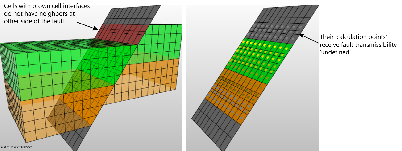
'Calculation points' of cells that do not have a neighbor at the other side of the fault will receive fault transmissibility 'undefined'. click to enlarge
All the properties generated with the Fault Seal Modeling workflow are stored in an auto-generated Surface Set with the name convention <name of the 3D Grid>-<name of the Fault Seal Model> (e.g., 3D Grid 1 - Fault Seal Model 1) and can be visualized in the 3D View.
Generated properties
The table below shows an overview of all the properties that can be generated with the Fault Seal Modeling workflow, and which are stored as properties of the point set as mentioned above.
| Workflow form | Generated property in JewelExplorer | Serves as input property for... |
|---|---|---|
| Clay Content | SGR hanging wall [fraction between 0 - 1] | Permeability calculation |
| SGR footwall [fraction between 0 - 1] | Permeability calculation | |
| SGR average [fraction between 0 - 1] | Permeability calculation | |
| SSF smear [any value] | Property 'SSF categorical' | |
| SSF shale bed average [fraction between 0 - 1] | Combination method 'Clay mixing, Clay smearing' | |
| SSF categorical [categorical] | - Combination method 'Clay mixing, Clay smearing' - Permeability calculation | |
| SGR - SSF combination [fraction between 0 - 1] | Permeability calculation | |
| Fault Permeability | Fault permeability [mD or m2] | Fault transmissibility calculation |
| Fault Thickness | Fault thickness [m] | Fault transmissibility calculation |
| Fault Transmissibility | Fault transmissibility [m3] | Stored in the Fault Seal Model which can be selected as input to reservoir simulation |
Additionally, three more properties are added to the point set when you select a Fault Seal Model as input to a reservoir simulation case and click Connect faults on the Faults and NNCs form in the simulation workflows (IMEX™, GEM™, STARS™, ECLIPSE™ and tNavigator™). These properties are for QC purposed only:
- simulation case name - CTR with FSM (= CTRtot)
- simulation case name - CTR without FSM (= CTRno fault)
- simulation case name - CTR Ratio (= CTRno fault / CTRtot)
CTRtot and CTRno fault are explained in section Faults and NNCs view.
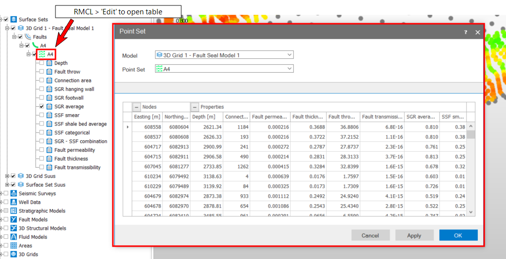
To display property values in table format, right-mouse click on the point set in the JewelExplorer to open its context menu and select Edit, see image below.
Links to the workflow steps
The Fault Seal Modeling workflow consists of the following steps:
Assigning the 3D grid and faults
Calculating fault clay content