Calculating fault clay content
With the Fault Clay Content form (model > Fault Seal > Fault Seal Modeling > Fault Clay Content) you calculate clay content in the fault zone and generate one or more clay content properties. Clay content is a requirement for the fault permeability calculation (next step of the workflow).
To calculate clay content, you can choose from three methods: (i) Clay mixing, based on Shale Gouge Ratio, or 'SGR' (an arithmetic mean of the fault-slipped Vshale); (ii) Clay smearing, based on Shale Smear Factor, or 'SSF' (in which smear continuity is defined from a cut-off value in displacement distance as function of source bed thickness); and (iii) a combination of results from 'SGR' and 'SSF'. Detailed information per method, including calculation examples, is given in section Clay content calculation methods.
The 'Clay mixing SGR' method works for both consolidated and unconsolidated impure sands and sand-shale interbeds (this method takes into account the average Vshale value of all the layers in the slipped sequence). Clay smear algorithms characterize how soft rock (i.e. the shale layers within the sequence) is sheared and squeezed into the fault zone. So the 'Clay smearing SSF' method is recommended for blocky clean sand-shale reservoir-seal pairs or clean sand reservoirs containing distinct significant shale beds. This generates local sealing where the clay smear is continuous on the fault plane, and leaves the fault open to flow in between the smears (a map of the fault surface permeability would look like a 'bar code').
The combination method combines both SGR and SSF. This is ideal for impure sandy sequences containing distinct shale beds and/or laterally variable facies motif (blocky to interbedded). In that situation, continuous clay smear will control the fault seal where the shale is robust or the motif is blocky, and SGR will control the fault seal where the sequence is dominated by sands or finer scale interbeds. This combination of algorithms generates a map of fault permeability on the model fault surface that is sealed where there is a smear and variably reduced permeability where there is SGR (SGR derived permeability values infill the gaps in the clay smear 'bar-code' pattern). This is illustrated in the image below, where the green layers represent shale layers (soft rock) squeezed in the fault zone.
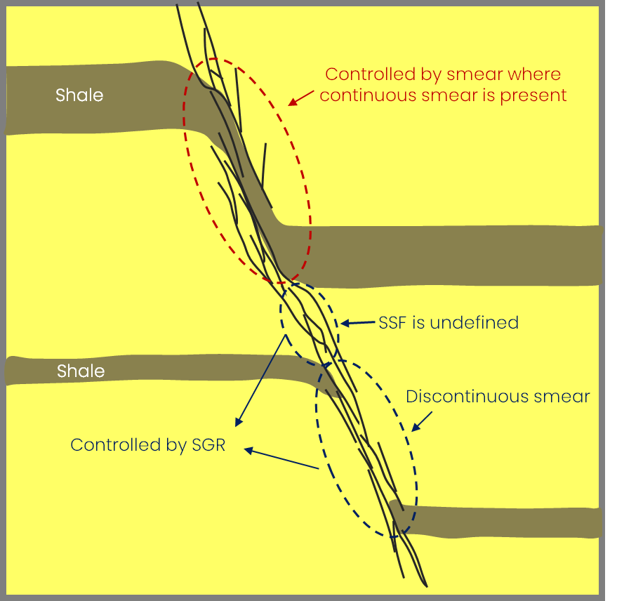
With the combination method, in sections where squeezed soft rock is continuous in the fault zone (see red circle), Shale Smear Factor controls the clay content, while Shale Gouge Ratio controls the clay content where this is not the case (see blue circles). click to enlarge
To calculate the clay content
- At the top of the form, in the Model drop-down list, select the relevant Fault Seal Model.
- In the Vshale property drop-down list, select the Vshale property of the 3D Grid (only Vsh properties of the 3D Grid that was selected on the Assign Data form are available for selection).
- Fault offset Select a geometric property, i.e. 'Fault throw' or 'Fault dip displacement'. When 'Fault throw' is selected, this measures the vertical component of displacement (Δz in image below); when 'Fault dip displacement' is selected, this measures the down-dip displacement component, parallel to the fault plane (Δz' in image below). 'Fault throw' is only used as an approximation for displacement where the faults are steeply dipping (>60 deg). Otherwise use 'Fault dip displacement' which is far more accurate where faults are shallowly dipping (60 deg or less), or if the faults have a listric (curved) shape. 'Fault dip displacement' is also strongly recommended for SSF clay smear calculation, since this algorithm is based on shale offset distance within the fault plane.
-
Assigning a method Various methods to calculate clay content are available. Before you select a method, it is recommended to read Clay content calculation methods, which explains the background to each of the methods, including a calculation example and the associated properties generated in the JewelExplorer.
Before you select a method, note that you can assign multiple methods on the form simultaneously. Only when clicking Apply/OK at the base of the form, the clay content calculations (one or multiple, depending on your selection) are performed and the properties generated. To assign one or more methods, follow the steps in the relevant section(s) below:
- In the table on the form, click on 'Clay mixing'. Upon clicking, a Method drop-down appears in the Settings section at the right side of the form.
- Select SGR from the drop-down. The method is added to the 'Method' column in the table.
- If you do not want to assign more methods, continue with step 5 below.
- In the table the form, click on 'Clay smearing'. Upon clicking, a Method drop-down appears in the Settings section at the right side of the form.
- Select SSF from the drop-down. Upon selection, SSF is added to the 'Method' column in the table and the following controls appear in the 'Settings' section on the right:
- Vshale cutoff Enter a Vshale cutoff value to define shale and non-shale. Only layers within the slipped sequence that meet this Vshale cutoff criterium will be incorporated in the SSF calculation.
- Continuous smear cutoff Based on this value a categorical property 'SSF categorical' will be generated in the JewelExplorer: SSF values ≤ continuous smear cutoff become 'continuous' and SSF values > continuous smear cutoff become 'discontinuous'.
- Minimum shale bed thickness (Optional) It is recommended that you enter a minimum thickness for shale layers to be included in the SSF calculation: all layers within the slipped sequence that are thinner than this value will be excluded from the SSF calculation.
- If you do not want to assign more methods, continue with step 5 below.
- Follow the steps for Method 1 'Clay mixing' above.
- Follow the steps for Method 2 'Clay smearing' above.
- Check the checkbox Combination clay mixing and clay smearing in the 'Settings' section on the right. Upon checking the box, two sets of radio-buttons are enabled:
Clay Mixing Value for Discontinuous Smear Here you select the clay content values to be assigned to the 'discontinous' calculation points of property 'SSF categorical' (i.e. these are the calculation points with an SSF value greater than the continuous smear cutoff value, see also image below). The three options you can choose from are derived from the SGR calculation under 'Method 1 SGR':
- SGR average Average of the hanging wall and foowall SGR of the slipped sequence at the point of calculation (i.e. property 'SGR average', auto-generated with Method 1 SGR. which you can visualize it in the 3D View). This is generally recommended.
- SGR hanging wall Hanging wall SGR of the slipped sequence at the point of calculation (i.e. property 'SGR Hanging wall', auto-generated with Method 1 SGR. which you can visualize it in the 3D View). Special cases.
- SGR footwall Footwall SGR of the slipped sequence at point of calculation (i.e. property 'SGR Footwall', auto-generated with Method 1 SGR. which you can visualize it in the 3D View). Special cases.
Clay Smearing Value for Continuous Smear Here you select the clay content values to be assigned to the 'continuous' calculation points in property 'SSF categorical' (i.e. the calculation points with an SSF value lower than or equal to the continuous smear cutoff value, see also image below):
- Use constant A constant Vshale value will be assigned to the calculation points. Enter the Vshale in the entry field on the form.
- Use Vshale cutoff value The Vsh cutoff value as defined in the settings section for 'Method 2 SSF' on the form (optionally click on Method 'SSF' in the table on the form to verify this value).
- SSF shale bed average Vshale of the shale layer with the lowest SSF value (i.e. the thickest shale layer) in the slipped sequence, as calculated with Method 2 SSF. You can verify these values by visualizing property 'SSF continuous clay' (once it has been generated) in the 3D View.
Method 1: Clay mixing (SGR)
For more info on the underlying calculations, see Clay mixing (SGR).
Method 2: Clay smearing (SSF)
For all fault seal methods you need to have calculated the required geometric property, i.e. 'Fault throw' or 'Fault dip displacement'. See the overview table in Requirements and input.For more info on the underlying calculations, see Clay smearing (SSF).
Property 'SSF categorical' is used in Method 3 'Clay mixing, Clay smearing' where you can assign alternative clay values to each of the two categories. The property can also be used in the fault permeability calculation, where you can directly assign a permeability value to each of the two categories.In case the slipped sequence of a calculation point contains too little clay (or when the minimum shale layer thickness is not reached), SSF smear cannot be calculated and the calculation point is set to undefined.Method 3: Combine Clay mixing, Clay smearing (SGR, SSF)
For all fault seal methods you need to have calculated the required geometric property, i.e. 'Fault throw'. See the overview table in Requirements and input.For more info on the underlying calculations, see Clay mixing, Clay smearing (SGR-SSF).
Method 3 combines results from method 1 'Clay mixing' and method 2 'Clay smearing'. For that reason you first have to assign each of the methods 'Clay mixing' and 'Clay smearing' before you can assign the combination method (i.e. the controls to assign the combination method are disabled until the other two methods are assigned). To do this:
When you have finished assigning the two methods, click on 'Clay mixing, Clay smearing' in the table. The controls for this method which appear in the 'Settings' section on the right are now enabled and the form should look like this:
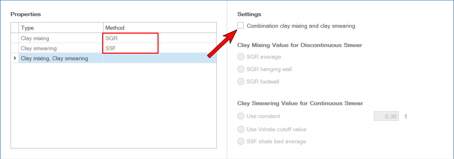
Only when the two methods SGR and SSF have been assigned in the Method column, the checkbox 'Combination clay mixing and clay smearing' gets enabled. click to enlarge
-
At the base of the form, click Apply to do the calculation and keep the form open or OK to do the calculation and move to the next step of the workflow Calculating fault permeability. Upon clicking, the clay content properties are calculated and added to the respective point set(s) in the 'Fault Seal' surface set in the JewelExplorer. Depending on your choice of method, the following properties are generated:
For method 'Clay mixing (SGR)' the following properties are added to the JewelExplorer:
- SGR average
- SGR hanging wall
- SGF footwall
For method 'Clay smearing (SSF)' the following properties are added to the JewelExplorer:
- SSF smear
- SSF shale bed average
- SSF categorical
For method 'Clay mixing, Clay smearing (SGR,SSF)' the following property is added to the JewelExplorer:
- SGR - SSF combination
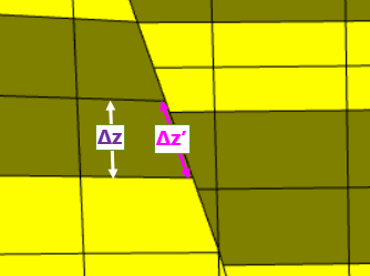
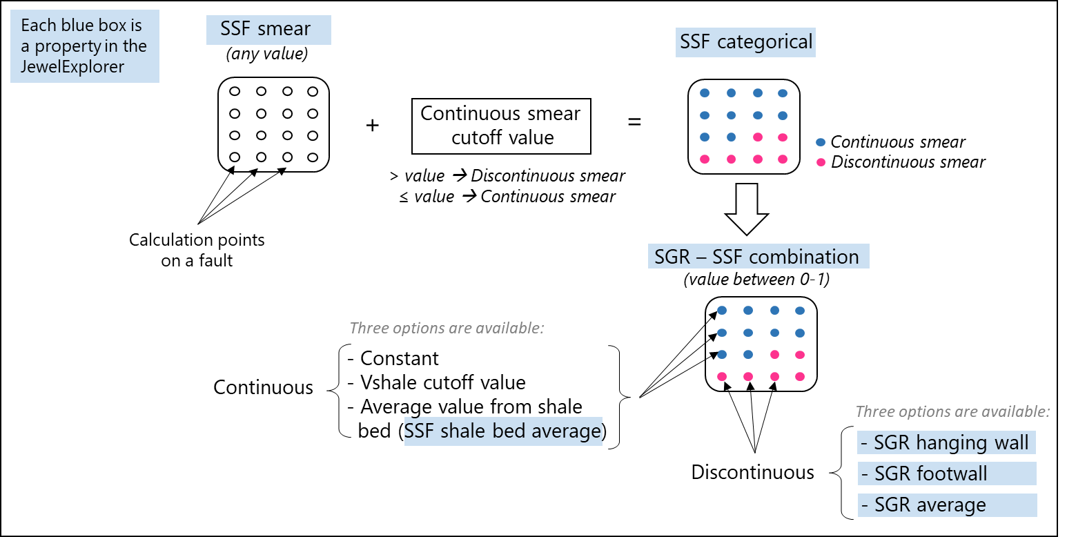
Diagram showing how the properties (indicated in blue) as generated with Method 1 and 2 come together in combination Method 3. Properties 'SGR average', 'SGR hanging wall', 'SGR footwall' are generated with 'Method 1 SGR'. Properties 'SSF smear', 'SSF categorical and 'SSF shale bed average' are generated with 'Method 2 SSF'. The results are combined in property 'SGR - SSF combination', which is the output property of Method 3. click to enlarge