Creating point sets
Fault stability analysis investigates the normal and shear stress that can act in the subsurface on each fault patch. The discrete analysis workflow uses triangulated surfaces for fault representations. The direction of the normal stress is orthogonal to these triangles, whereas the direction of the shear stress lies parallel to the plane of these triangles. The direction of the shear stress is used to indicate the direction of the potential movement of the individual elements.
The Create Point Sets tool (model > Fault Stability > Create Point Sets) is a QC tool, helping you to automatically display the normal or shear stress components (as calculated with the Discrete Analysis workflow). The form will create point sets based directly on the nodes of the tri-meshes (when the fault stability model is in 'Node' mode), or based on nodes created at the triangle centers (when the fault stability model is in 'Triangle' mode). The form also applies pre-defined shape graphics to the point sets (normally to be done manually with the Shape Graphics tool) to produce arrows on the fault planes (see image below). This ensures a fast and easy interpretation of the orientation and magnitude of the stresses with respect to the fault surfaces.
You should be aware that the direction of the shear stress arrow calculated for individual fault triangles is not necessarily a measure for the direction of a potential fault movement. A potential movement is governed by an entity of elements rather than individual triangles. If, however, the bulk of shear arrows point into one direction, a general direction can be anticipated.
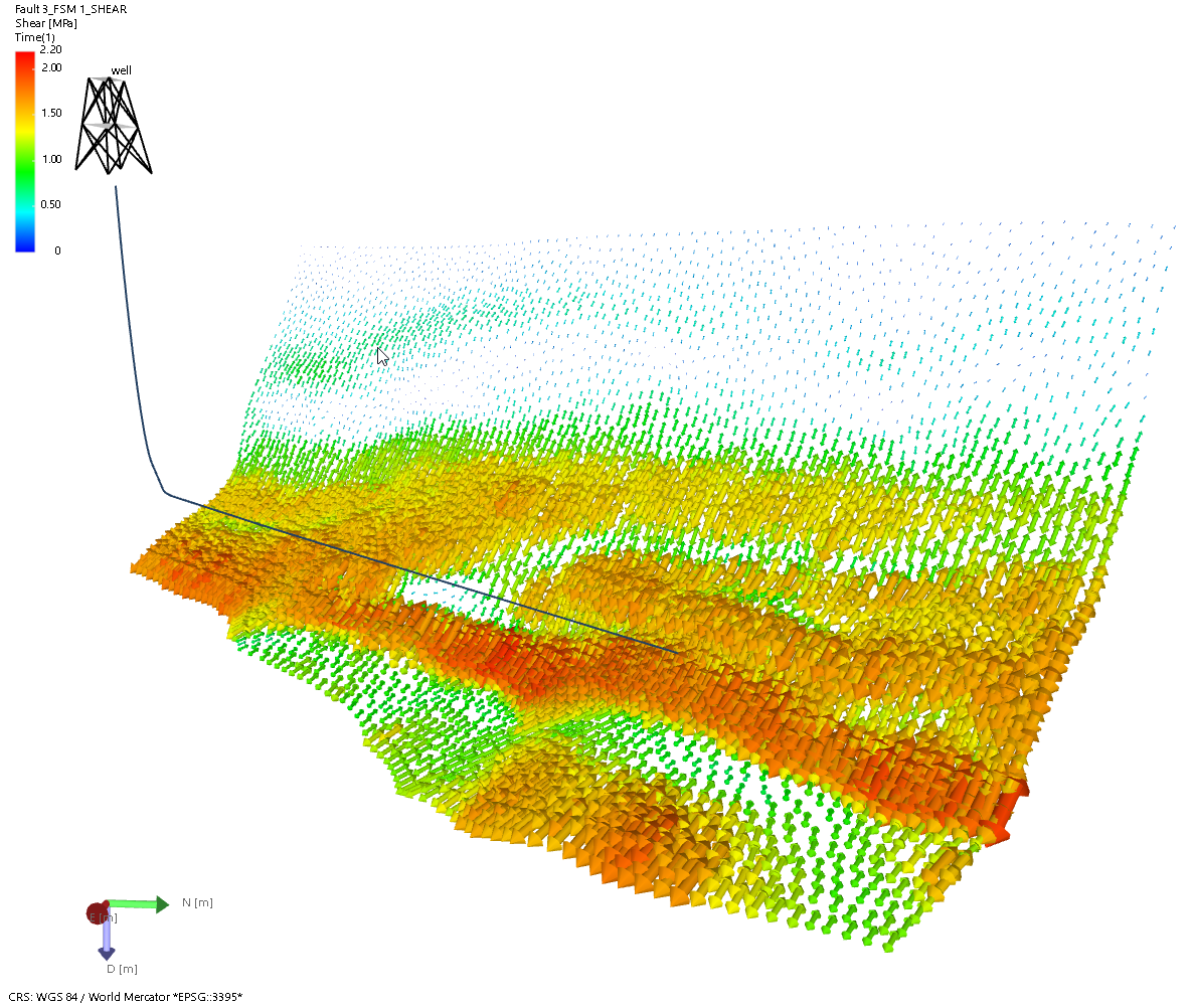
Point set with the shear stress property displayed as arrows. The automated settings for graphical display ensures an easy interpretation of the shear or normal stress components (the arrows indicate the orientation of the stress while size and color represent the stress magnitude). click to enlarge
To create point sets
- Open the Create Point Sets form and select the relevant Fault Stability model at the top of the form. Only Fault Stability Models can be selected as input to this form.
- Under Type select whether you want to analyze (and create point sets for) shear stress or normal stress (select 'Shear' or 'Normal' respectively).
- Depending on your choice in step 2, select the input properties:
- 'Shear' - In the Azimuth shear and Dip shear drop-down fields, select the directional properties of your shear stress. In the Magnitude shear drop-down field, select the property representing the magnitude of your shear stress. If you followed the Discrete Analysis workflow to generate the fault stability properties, 'Azimuth Shear', 'Dip Shear' and 'Tau' are auto-selected respectively (they are read from the 'Fault Stability' folder located in JewelExplorer\<your fault stability model>). In case you have other directional and magnitude shear properties, you can select them if they are in the same folder and of type 'Dip azimuth', 'Dip' and 'Stress' respectively.
- 'Normal' - In the Magnitude normal drop-down field, select the property which represents the normal stress. If you followed the Discrete Analysis workflow to generate the fault stability properties, 'Sn, effective' is auto-selected on the form (it is read from the 'Fault Stability' folder located in JewelExplorer\<your fault stability model>). In case you have another normal stress property, you can select is if it is in the same folder and of type 'Stress'.
- Click Apply or OK at the base of the form to create the point set(s) with the stress component properties. The point sets are stored next to the tri-meshes under the Fault Stability model and contain the following properties:
- For shear stress: 'Azimuth Shear', 'Dip Shear', 'Shear'.
- For normal stress: 'Azimuth Sn', 'Dip Sn', 'Sn'.
Visualize the generated point set property in the 3D View by selecting the point set and the property in the JewelExplorer, e.g. 'Shear'. Notice how default settings (e.g. the colorset) of the graphical display enables easy interpretation of the shear or normal stress.
You can change these default settings with the Shape Graphics tool. The Shape Graphics tool can be accessed via Workspace > Tools or via the Point Set's context menu Display Settings > Advanced Shape Options.