Solving fault intersections
Use the Solve Fault Intersections form (Model > Faults > Solve Fault Intersections) to define the topology of an inter-connecting fault network. This can be done using
- retraction in case a fault extends beyond its intersection with another fault.
- extension in case a fault falls short of its intersection with another fault.
The overall aim of this operation is to create a watertight fault model, where the intersections between all faults do not show gaps. Aiming for a watertight model is very important, especially for the construction of the 3D grid at a later stage. Use the Settings tab on the form to define the maximum allowable retraction and extension distances. You can define different values for different faults.
To solve fault intersections
First, click Calculate to calculate the intersections in your fault model; when the calculation is finished and intersections are found, the table on the Intersections tab is populated with the identified intersections. In the JewelExplorer, the Fault Model > Intersections folder is created, containing the intersections. A preview of any intersections selected on the form is shown in a dedicated Solve Fault-Fault Intersections 3D View, with the proposed extension or retraction.
You can review every proposed intersection in the 3D View, by clicking anywhere in the row of the intersection in the table on the Intersections tab. The checkboxes in the 'Select' column allow you to exclude intersection relationships from being applied. Only the intersections that you select by checking the 'Select' box will be solved. Alternatively you can check the intersection in the column 'Block'. This will exclude the intersection relationship from being solved. Here, the intersection relationship will still be visible in the 3D View, but it will be rendered with gray dotted lines to show that it is inactive.
Colors in the dedicated Solve Fault-Fault Intersections 3D View
- Extensions are rendered in light blue arrows,
- Retractions are rendered in yellow arrows.
- Intersection segments recognized as internal intersections will obtain red nodes.
- Sections interpreted as watertight will have green nodes.
- Nodes related to extension or retraction segments will obtain node colors in relation to the corresponding faults.
You can change the sequence in which the fault intersections are being resolved. In some cases, a fault/fault relationship cannot be judged by the application on which segment to retract. If you have two crossing faults forming an ‘X’ shape, for example, you can retract either of the faults. With the Swap button, you can change the Major fault into the Minor one and vice versa.
When you click the Apply button, the application will attempt to resolve the intersection relationships that you have checked in the 'Select' column. An attempt will be marked in the Handled column with a green checkmark. Please review the Dominant Type column listing the watertight percentage for an indication on the quality of the solved intersections before leaving this form. Intersections do not necessarily need to be 100% watertight. However, you should not allow small internal gaps. If repeating the workflow does not resolve internal gaps, use the extend/retract tools from the Editing Tools to manually resolve the intersection relationship. Alternatively, the Tools section of this workflow offers further assistance under the Structure Builder icon.
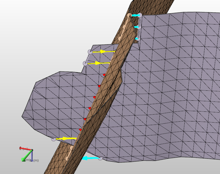
A fault intersection before solving. The nodes have the colors of their respective fault, while arrows indicate extension cyan) and retraction (yellow) click to enlarge
Node and arrow colors
In the preview, different colored arrows are used to indicate the retractions and extensions. For retractions, the arrows are yellow, while for extensions the arrows are cyan. The nodes on the faults are in a color that is slightly lighter than that of their associated fault.
Red nodes mark an intersection which cannot be resolved by retraction since the retraction required to do this exceeds the retraction distance limit (defined on the Settings tab of the Solve Fault Intersections form). Increase the allowed retraction distance to resolve such sections as well.
To make the nodes and lines more visible, you can adjust the line width, the marker diameter and the marker border width of the intersections using the Display settings form.
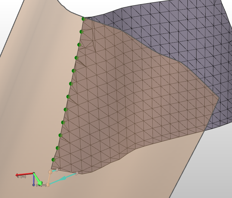
The fault intersection solved. The green nodes indicate a watertight connection click to enlarge
Once you apply the solve fault intersection, green nodes indicate a watertight connection. Nodes that are not yet resolved remain in the color of their associated fault.
Settings tab
Part of the data in this table is for information only. In the 'Intersection' columns, user-defined settings limit the distance that a tri-mesh can be retracted, extended, or refined to avoid creating additional mismatches.
Surface
Name The name of the selected surface.
Type Displays the (geological) type of the surface.
Dimensions
Area Displays the surface area of the object.
Length Displays the length of the surface.
Height Displays the height of the surface.
Intersection
Retraction Distance Enter the maximum retraction allowed for retraction. If you see red nodes in the fault intersection preview, you can increase this value. (Red nodes in the preview indicate that the retraction required is greater than the value set here.)
Extension Distance Enter the maximum distance for allowed for extension.
You can also set the retraction or extension distance for all intersections at once. Right-click anywhere in the table to open a context menu.
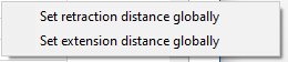
Set a global distance value for either the retraction or the exentsion distance using the options on the context menu click to enlarge
After making a selection, the Set Global Value form will open, where you can fill in the distance to use for all retractions/extensions.
Intersections tab
The table on the intersections tab provides information about the intersecting faults, and allows you to change the order in which intersections are being resolved. The column header has a 'plus' sign that can be clicked to reveal additional columns, which are described below. You can right click in a row or column for more options.
To better view intersecting surfaces, you can click on a fault intersection in the table to open a Solve Fault-Fault Intersections 3D View. In this view, you will see the two faults that create the intersection, and all other intersections on both surfaces. All the intersections that are shown in this view are checked in the JewelExplorer as well. To display the surfaces of those intersections, you can use the context menu of an intersection.
Selecting an intersection in the JewelExplorer also changes the select state on the Solve Fault Intersections form and the Solve Fault-Fault Intersections 3D view, and vice versa.
The selected intersection can be recognized in the view, it will have a slightly larger marker diameter and line width.
Select Check the box to select the intersections you want to solve. The selection is propagated to the JewelExplorer where you set the visibility. Right click anywhere inside the table to open the context menu with the following option: Auto-fill order based on current sorting. First sort the table using a column header, next select this option to change the order in which the intersections are solved into the current sorting order.
Order Indicates the order in which the intersections will be solved. If you want to change this order you can do this either manually in this column, or first sort the table using a column header and then use the auto- fill option on the context menu. The ordering will be saved, you can click Calculate, and when you return to this form later the new ordering will be preserved.
Handled This box is empty upon opening the form. When you have solved an intersection a green check mark appears.
Dominant Type This column is for information only. It will give the percentage of the proposed/current intersection states. There are 4 intersection states that can be listed, in combination with a percentage:
- Internal
- Extension
- Retraction
- Watertight
How to solve the different intersection states
76% Internal - 76% of the detected intersection has the internal status. This means the minor fault cuts through the major fault with a distance that is larger than the retraction distance as specified on the settings tab. Applying the current retraction will not solve the intersection. To solve the intersection, you must increase the retraction distance on the settings tab. The remaining 24% of the intersection can have any other state.
88% Extension (Retraction) - 88% of the detected intersection requires extension from the minor to the major fault to make it watertight. Applying the current extension, meaning extending the minor fault with a distance as specified on the settings tab, will not solve the intersection. To solve the intersection, you must increase the extension distance on the settings tab. The remaining 12% of the intersection can have any other state.
90% Watertight - The major and minor fault are connected for 90 % of the detected intersection. To reach 100%, you can click Apply, all intersections that are selected are solved, and inspect the results. Every time you click Apply, the detection of the intersection is refreshed.
Major Fault Displays the name of the major fault of the selected intersection.
Swap If you click Swap, the major fault and the minor fault are swapped. The name of the intersection is updated immediately in the JewelExplorer.
Minor Fault Displays the name of the minor fault of the selected intersection.
Max Extension Distance The max extension distance calculated by the application. This information is read-only.
Max Retraction Distance The max retraction distance calculated by the application. This information is read-only.
Length The length of the fault after the proposed alterations. This information is ready-only.
Segments The number of segments produced by the extension/retraction process. This information is read-only.
Block To exclude an intersection from the selection of faults to be solved with the proposed extension or retraction, check the Block option. In the 3D View, the proposed extension or retraction will be shown as a gray dotted line, but will not be solved. If you uncheck the Block option, the intersection can be selected again.
Intersections context menu
To open the context menu of an intersection you can either right click on the intersection in the JewelExplorer, or right click the intersection in the Solve Fault-Fault Intersections 3D View.
Name The names of the two intersecting faults are given. To change the name of an intersection double click on the intersection in the JewelExplorer.
Hide You can use this option to hide or show an intersection in the 3D view.
Show Related Surfaces If you select this option, all surfaces that intersect with these faults are displayed.
Show Related Surfaces Only, Hide Others If you select this option, only the two faults that are intersecting are displayed.
Click Apply to solve the fault intersections or click OK to solve the fault intersections and close the form and proceed to model validation. If you are not satisfied with the result, you can either go back to the settings tab on the solve fault intersections form and change the retraction and/or the extension distance, or use the editing tools on the floating palette.