Creating and editing wells with the Well form
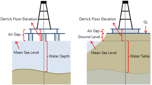
Two diagrams, showing the datums for an offshore well (left) and onshore well (right).
With the Well form you can create new wells by entering geographic or projection coordinates and trajectory data, or inspect and edit the data of wells already existing in your project
You may also wish to create a synthetic wellbore with the goal to analyze properties at specific locations in your model. Using a simple well trajectory (that need not represent a realistic well) through such points you can create a pseudolog, make a cross-section, or use the well object for other analysis or modeling options.
You can also create a well graphically in a view by using the graphical tools in the floating palette. See Specifying a well plan, Graphically creating wells and Graphically designing wells and well pads.
As an alternative to opening the Well form via the strip, you can also right click on the well in your 3D View or in the JewelExplorer and select Edit from the context menu.
Open the Well form. The Well form consists of three tabs, the Wellhead, Wellbore and Trajectory tabs, each of which contains the information of the well and wellbore that you are creating or have selected at the top of the form.
- To create a new well and wellbore - Select Create new from the Well drop-down list and type a name for the new well in the entry field below. Subsequently select Create new from the Wellbore drop-down list and type a name for the new wellbore in the entry field below. Proceed with the Wellhead tab, see below.
- To create a new wellbore for an existing well - Select the existing well from the Well drop-down list. Select Create new in the Wellbore drop-down list and type a name for the new wellbore in the entry field below. Proceed with the Wellbore tab (see below).
- To edit an existing well or wellbore - Select the existing well from the Well drop-down list and subsequently the existing wellbore from the Wellbore drop-down list. The Wellhead, Wellbore and Trajectory tabs on the form are auto-filled with all the known data for the selected well and wellbore, and can be edited.
General Settings
UWI Unique Well Identifier. Must be unique as a UWI attribute.
Name Well name. Must be unique as a Name attribute.
Display name Name of the well when shown in the user interface. In case you are creating a new well, the entry field is initially grayed-out but can be edited after the you have applied the form.
Location
Enter the coordinates of the well head as Easting/ Northing values or as Latitude / Longitude values. When you enter values for one convention, they are directly auto-filled for the other convention.
Site
Specify if the well is located Onshore or Offshore. Depending on your selection, you can define the following:
- Mudline/Water depth (Offshore well) Enter a value for the mudline depth or water depth, referenced to Mean Sea Level, see image below. A positive value means below Mean Sea Level.
- Water density (Offshore well) Enter the sea water density.
- Ground level (Onshore well) Enter a value for the ground level, referenced to Mean Sea Level, see image below. A positive value means above Mean Sea Level. Note that this value is for information only and not used for DFE calculation.
- Water table (Onshore well) Enter a value for the water table, referenced to Mean Sea Level, see image below. A positive value means below Mean Sea Level.
Following the above rules, for example, an onshore well drilled at a location below Mean Sea Level will have a negative value for Ground Level.
Wellbores Summary
At the base of the Wellhead tab, the Wellbores Summary table gives key information of all the wellbores that exist for the well that is selected at the top of the form. This table is for information only and not editable. When you want to make a change to the data for one of the wellbores, select the respective wellbore at the top of the form, open the Wellbore tab or Trajectory tab, and edit the corresponding field there.
General Settings
UWBI Unique Wellbore Identifier. Must be unique as a UWBI attribute.
Name Wellbore name. Must be unique as a wellbore name attribute.
Display name Name of the wellbore when shown in the user interface. In case you are creating a new wellbore, the entry field is initially grayed-out but can be edited after the you have applied the form.
Air gap Enter a value for the air gap, which is the distance between the DFE and Ground Level (Onshore well) or between DFE and Mean Sea Level (Offshore well), see image above. A positive value means above Mean Sea Level. Note that this value is for information only and not used for DFE calculation.
Spud date Optionally enter the spud date of the wellbore.
Operational status Put the status of the wellbore to On, Off or Unknown.
Trajectory Summary
At the base of the form, the Trajectory Summary table gives key information (i.e. Easting/Northing, Longitude/Latitude, MD and TVDSS) of the surface/KOP and bottom of the wellbore trajectory that is currently selected at the top of the form. This table is for information only and not editable. When you want to make a change to the data, open the Trajectory tab and update the corresponding field there.
General Settings
Derrick floor elevation Enter a value for the Derrick Floor Elevation (DFE), referenced to Mean Sea Level, see image above. A positive value means above Mean Sea Level.
Parent wellbore (Only enabled when the wellbore is a sidetrack) The wellbore from which the current wellbore sidetracks.
Tie-in/KOP MD For the main wellbore: the measured depth (MD) of the initial wellbore node point, relative to the well head location. For a sidetrack: the kick-off point from the parent hole. The KOP/MD is measured from the sidetrack DFE.
Tie-in TVDSS (Only enabled when the wellbore is not a sidetrack) The true vertical depth subsea (TVDSS) at the tie-in/KOP MD. Automatically set to -DFE (negative DFE). You can update this value.
Tie-in inclination (Only enabled when the wellbore is not a sidetrack) The inclination of the initial wellbore node point at tie-in/KOP MD.
Tie-in Azimuth (GN) (Only enabled when the wellbore is not a sidetrack) The azimuth (angle with the northing direction) of the initial wellbore node point at tie-in/KOP MD.
Tie-in Delta Easting (Only enabled when the wellbore is not a sidetrack) The distance in easting direction between the initial wellbore node point and the wellhead of the main borehole.
Tie-in Delta Northing (Only enabled when the wellbore is not a sidetrack) The distance in northing direction between the initial wellbore node point and the wellhead of the main borehole.
Status Select the status of the wellbore: Existing, Planned or Unknown.
Azimuth reference (For information only) The azimuth reference in JewelSuite Subsurface Modeling is always Grid North.
Scale factors (For information only) When a scale factor was applied during import of the well data, this field is set to 'On'. In all other cases, it is set to 'Off'. A scale factor can only be applied during import of the well data.
Interpolation When you check the box, you can interpolate the data in the survey table based on a user-defined interpolation distance. Note that this interpolation is only a visual aspect and does not change the underlying data. You can optionally copy-paste the interpolated trajectory data to an external application, e.g. Excel spreadsheet. Enter the interpolation distance in the MD interval entry field below. The minimum MD interval is 1 ft.
Survey
Show full trajectory for sidetrack (Only enabled when the wellbore is a sidetrack) When you select this box, the sidetrack trajectory data will extend to the surface, based on the sidetrack DFE. The parent wellbore name(s) will be shown together with the data in the table.
Trajectory definition Select whether you want to enter the wellbore trajectory as deviation survey data (MD, Inclination, Azimuth) or as position log (Easting, Northing, TVDSS). The other system's values will be auto-calculated and visible in the table.
Survey table
To enter the wellbore trajectory data to the table:
 Add a row Click the plus icon to add a new, empty row to the table, then enter the data in the empty row.
![]() Paste and add rows Paste data from your clipboard into the table (new rows are automatically generated). See 'Copy-paste' below.
Paste and add rows Paste data from your clipboard into the table (new rows are automatically generated). See 'Copy-paste' below.
![]() Delete row To remove a row, select a cell in the row and click the delete icon. You can multi-select cells to delete multiple rows at the same time.
Delete row To remove a row, select a cell in the row and click the delete icon. You can multi-select cells to delete multiple rows at the same time.
Copy-paste You can copy-paste Excel™ spreadsheet or tab-delimited data into the table. The data must use point (.) as the decimal separator and comma (,) as the thousands separator. Using comma as decimal separator will not import the data correctly and certain data columns may not be recognized.
-
If you paste the data using Ctrl+V, make sure you have created the correct amount of new rows before you paste the data, else not all data might be pasted. You can create new, empty rows with the icon located above the table.
-
You can directly paste the data into the table without the need to create empty rows first. To do this, copy the data to your clipboard, then select any cell in the table and click the
 icon. The data is pasted below any existing data in auto-generated rows.
When you are finished creating or editing the well or wellbore, click Apply or OK to create the well or save the edits. If there are any problems with data consistency, a message will pop up and also be shown in your Output Information (Workspace > Panes > Output information). In case of a new well or wellbore, it will appear in the JewelExplorer under the Wells item, and all views that show wells.