Creating tri-meshes with triangulation
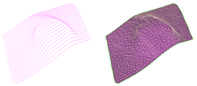
Triangulation: Input polyline set and resulting tri-mesh click to enlarge
Use the Triangulate form to triangulate the polyline sets or point sets. Triangulation automatically creates a tri-mesh across contiguous polylines or point sets by creating triangles between the nodes. The form displays all the polyline sets and point sets available in the selected source. You select which objects to triangulate, and then perform the triangulation using the specified triangulation settings. If you are working with faults, see also the fault and fault centerline creation features.
- At the top of the form, select the model to work with.
-
Specify the type of the polyline sets or point sets to triangulate:
Faults Show only polyline sets and point sets of the type fault.
Horizons and unconformities Show only polyline sets and point sets of the type horizon or unconformity.
Intrusions Show only polyline sets and point sets of the type intrusion.
-
From the list of the available objects of the selected surface type in the model, select the surface type of the object to be triangulated. Check the individual check boxes, or right-click the column header and make a selection from the context menu.
If you want to filter out polyline or point sets which have already been triangulated from the list, you can remove them from the list by checking the check box Show untriangulated sets only.Settings tab
- Control the triangulation with the following options on the settings tab:
- There should be little mis-tie between polylines crossing each other.
- Polylines that can be closed should be closed, i.e. if a polyline is interpreted on a time or depth slice cutting through an intrusion, the polyline should represent the closed outline of the intrusion’s intersection with the slice.
- Strange angles in the interpretation.
- Polylines that cannot be placed on a single 3D plane.
- Crossing lines which are within the specified tolerance. These lines are considered to be connected.
- Crossing lines where a connection is expected but not found within the specified margin.
- Click OK to triangulate the selected polyline sets.
Objects tab
Honor polyline segments All polyline segments will be available again as edges in the tri-mesh.
Simplify input lines If desired, you can simplify the polylines by checking the Simplify input lines box and then specifying a Lateral and Vertical tolerance. This will remove unnecessary nodes while limiting the amount of structural change that is tolerated in the polyline curvature in the vertical (Z) and lateral (X/Y) directions.
The difference with this option, compared to the same option in the Polyline Operations panel, is that the polyline nodes are not removed from the input data. The simplify option uses less nodes during triangulation, but does not change the input polyline set.
Refine input lines Refining the input polyline sets is possible by checking the Refine input lines box and specifying a Segment length. Additional nodes will be added to the input polyline sets which will make sure the resulting triangulation consist of more detail.
By enabling this option, the polyline set will be refined internally and the original polyline set will be unaltered. This is the only difference with the refinement step on the first panel.
Estimate boundary Select this option to access the various boundary options. When the option is not checked, a convex triangulation will be applied, which means that the biggest border around all polylines will be used, based on the input polylines.
Convex hull A convex hull will be created around the data points. In general a good method when dealing with horizons.
Fit to data – area fit, no gaps An algorithm that closely follows the input data and allows concave shapes but no gaps. The result is influenced by the step dimensions of the input area.
Fit to data – tight fit An algorithm that most closely follows the input data and allows gaps to occur. This method is the most accurate one, as far as input data is concerned, you should decide whether you want to apply this method and repair the surface later using the tri-mesh editing tools, or use a less accurate triangulation method.
Boundary polygon An option to limit the lateral extent of the output surface to a boundary. The boundary needs to be a closed polyline (polygon) stored in the Data > Boundaries folder. (If you don't have a boundary polygon, you can create one using the Workspace > Editing Tools ('Add Polyline Set'), then change it's 'Type' into 'Boundary' in the Property Inspector.) For more information about boundaries, see Boundaries and Feature Sets.
Cut remaining intersections Select this option to cut away the remaining surface-surface intersections after triangulation. There are three settings which can be specified:
Gap size defines the size of the gap which will be created around any remaining intersections.
Dip By specifying a dip threshold value, the algorithm will only cut away triangles which have a dip property value larger than the specified value.
Smoothness By specifying a smoothness threshold value, the algorithm will only cut away triangles which have a smoothness property value larger than the specified value.
Projection normal settings The triangulation algorithm requires that the polylines are projected onto a plane. An optimal projection vector is computed automatically for each polyline set and is called the default projection vector. Sometimes it is desired to override the default projection vector, which can be done with this user control.
Dip The Dip value of the projection vector.
Azimuth(GN) The Azimuth (angle with Northing direction) of the projection vector.
Reset to default The dip and azimuth values of the projection vector are reset to the values of the (auto-calculated) optimal projection vector. Note that when you selected more than one fault on the Objects tab, the entry fields for Dip and Azimuth stay empty when clicking 'Reset to default', however, the projection vectors are reset to default values for each of the selected faults. You can review these values by clicking on the arrow in the Dip and Azimuth fields.
Set from view The current orientation of the active 3D View (where the projection vector is the imaginary line between your eye and the (orthogonal) polyline set) is used as projection vector.
When using the Intrusions option as type, the controls in Settings are adjusted to address the specific needs of triangulating surfaces that bend back on themselves. One difficulty with such surfaces is that triangulation cannot be done with a single projection vector. Local vectors can only be defined if the polyline input satisfies the following conditions:
The options in Settings are meant to help identify input conditions that cannot be handled by the triangulation method. Intersection points calculated between crossing polylines are shown in the 3D View and are listed on the form. The options include:
Maximum distance crossing lines The distance specified in this input field is used as threshold. All polylines which are interpreted on intersecting planes are considered to be connected when the distance between the lines is smaller than the given threshold.
Re-validate When enabled, the intrusion polyline set is automatically re-validated after the polyline set has been modified.
Validate You can use validation to detect problems in the interpretation that may result in strange results in the triangulation. Therefore it is recommended to validate the polyline set before performing the triangulation of an intrusion. The following problems can be detected in the validation step:
The validation results are listed on the form. Double-click on a line in the list to hide all polylines except the one in question and move the focus of 3D view rotation to the location of the issue. Select Ignore if you think that the issue does not need to be resolved; otherwise use polyline editing tools like close polyline, remove node, remove segment or move node to make the local geometry unique. Note that it is possible to control the visibility of polylines with dedicated options in the context menu. Options like show crossing lines can be helpful in displaying those data relevant for deciding on the current issue. Revert to all polylines being visible by selecting the respective context option or by leaving the Triangulation form.
Solve active Solves the problems in the list. Not all issues can be validated. Some problems in the dataset might require additional manual editing.
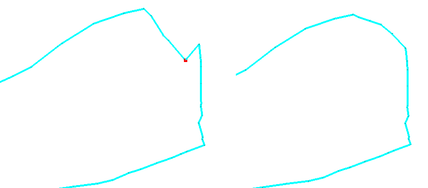
Example of a problem detected in an intrusion input polyline set click to enlarge
In this example, the red dot marks a node in the polyline set which contains a sharp angle. Using the Editing tools, you can move or remove nodes of the polyline set. By pressing the space bar, the node movement is restricted to the plane in which the line was interpreted. This allows easier movement than the 3D cursor and prevents problems which will arise when a node is moved outside the original plane.
After completion, the tri-meshes are available in the JewelExplorer and shown in the 3D View.
If you need to edit the tri-meshes after the triangulation, you can do this using the Tri-mesh Tools in the same strip, or in Tools > Editing Tools.