Ribbing tri-meshes
Use the Rib Tri-mesh form (prepare > Post-Processing Tools > Tri-mesh Tools > Boundary > Rib Tri-mesh) to create a polyline set from a tri-mesh representation. Other boundary tools are also available, and allow you to smooth and simplify tri-meshes. You need to have an area to use this tool, unless your input tri-mesh exists in a Seismic Interpretation.
- Select the model.
- Select the tri-mesh(es) for which you want to create a polyline set.
- Optionally (only enabled when the selected source for your input tri-mesh is a Seismic Interpretation) check the Use the resolution of the input seismic interpretation. When you check this box, the 'resolution' of the polyline set (i.e. the lateral distance between the output polylines) is automatically set to the resolution of the seismic survey.
- Select an Area.
- Select an output folder. By default, the model that you selected in step 1 is listed as the output folder. You can select another model from the drop-down list.
- Click OK to create the polyline set and close the form, or click Apply to create the polyline set and keep the form open. If you select the Data folder as the output folder, the output polyline set is stored under a newly created event (with the same name as the input tri-mesh) in the Data folder of the JewelExplorer. A suffix which is related to the name of the tri-mesh folder will be added to the name: _SI for Seismic Interpretation, _SS for Surface Set, _IM for Import and increments (1, 2, etc.) when the input tri-mesh is in the Data folder. If the output folder is the same as the model that you have selected at the top of form, the output polyline set is stored under the selected event. In case a polyline set already exists for the event, you have the option to overwrite the existing polyline set.
How the area is used
Unless you checked the Use the resolution of input seismic interpretation checkbox, you must select an Area. The step length of the Area is used to define the lateral distance between the output polylines. Where the area box and the tri-mesh do not intersect (e.g. the area box 'floats' above the tri-mesh), a vertical projection of the area box is used. For parts of the tri-mesh that fall outside of the (vertically projected) area box, no distance can be defined and polylines will not exist in those parts (see images below). Note that the Area does not crop the polyline set; the edge of the input tri-mesh will form a polygon in the output polyline set.
The output polyline set will be in either the I or J direction, depending on the maximum average dip of the input tri-mesh.
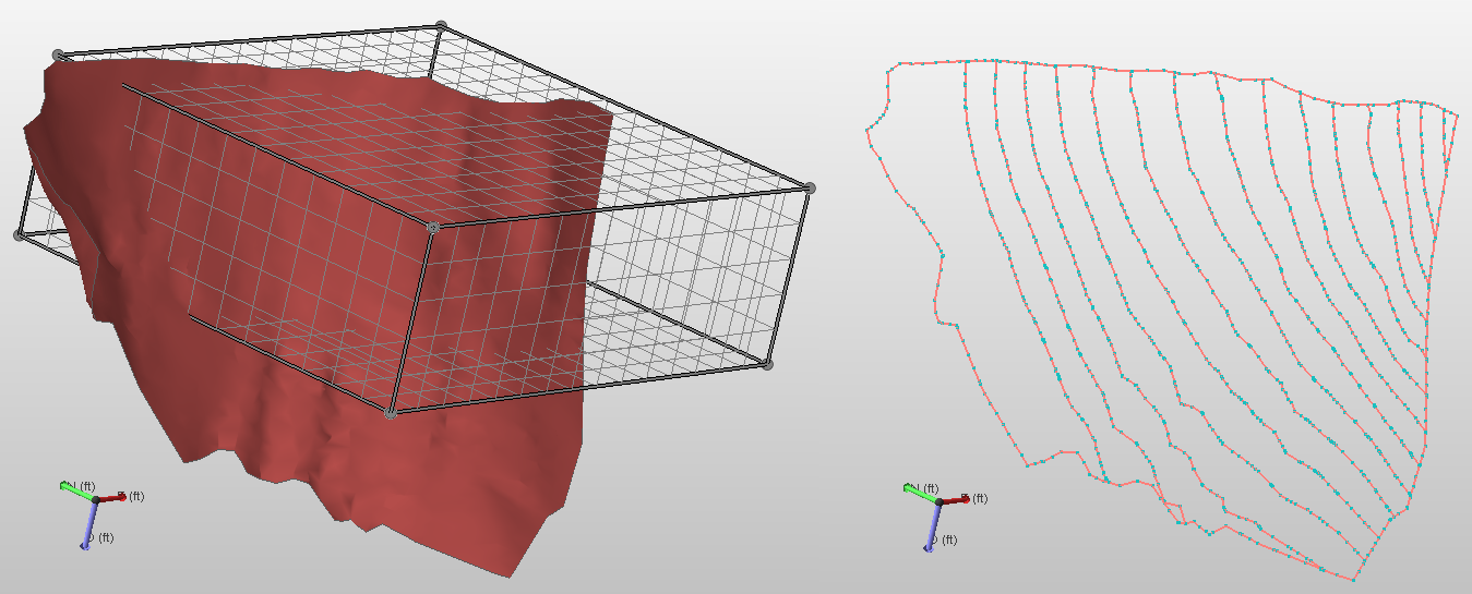
Polyline set created by ribbing a tri-mesh. click to enlarge
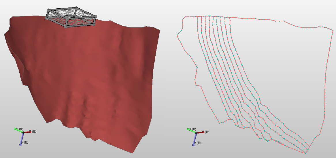
Another example of polyline sets created by ribbing a tri-mesh. After 'vertical projection 'of the area box onto the tri-mesh, polylines are defined within that area and extended towards the edge of the tri-mesh. click to enlarge