Assigning data to a seismic interpretation
In the second step in the Seismic Interpretation workflow (prepare > Seismic), you assign surfaces to a seismic interpretation (you can also use the form to change the resolution of a seismic interpretation, see further below) in JewelSuite Subsurface Modeling. For each surface, you can select which geometric representation to assign if it has more than one. You can select from the following geometric representations: polyline sets, 2D grids or tri-meshes.
You can select surfaces from various sources: from another seismic interpretation if it belongs to the same 'Survey' and domain, from a surface set (only available if the seismic interpretation is in depth domain) or from the Imports or Data folder. Also, you can select a surface from an already existing fault model or structural model. You can choose to select surfaces from more than one data source, allowing you to mix and match surfaces as needed.
At the end of the assign data step, your output surfaces will consist of the following representations:
- For horizons and unconformities: 2D grids and/or polyline sets, even when your assigned surfaces have a tri-mesh representation.
- For faults and intrusions: polyline sets only
When you assign surfaces to a seismic interpretation, polyline sets will be copied but 2D grids and tri-meshes will be resampled. The following resampling rules apply:
- The target resolution is a multiplier of the survey resolution and defines the output resolution for the assigned, resampled surfaces (see Target at the base of the form).
- It is recommended to assign 2D grids that have a compatible resolution (i.e. their resolutions are a multiplier of the survey resolution) to avoid uncertainties involved in snapping nodes over large distances (see schematic examples below). For instance, when you have a seismic survey with a resolution of 50x50, a 2D grid with a 25x25 resolution is compatible, but a 2D grid with a 37.5x37.5 resolution is not. When you have an incompatible 2D grid resolution, a warning icon will appear in the table in the Inline/Crossline Step columns.
- Node snapping occurs during resampling. As such, it is recommended to set a target resolution (with the Factor field at the base of the form) which is coarser than, or equal to, the input 2D grid resolution, to avoid introducing excessive undefined values (see schematic examples below). When you have 2D grids with a coarser resolution than the target resolution, a warning icon will appear in the table in the Inline/Crossline Step columns.
- When the data is not in the same area as your seismic survey, any data outside the seismic survey area is not used. A surface will be assigned only in the area of the seismic survey.
- If you are assigning a 2D grid that already has a (lattice) resolution (i.e. index data), JewelSuite checks whether the indices fit within the ranges of the Seismic Interpretation.
- When the 2D grid indices fall completely outside of the Seismic Interpretation, the 2D grid cannot be assigned.
- When the 2D grid indices fall partly outside of the Seismic Interpretation, the compatible inline/crossline indices will be assigned.
You can also use the Assign Data form to change the resolution of a seismic interpretation, without assigning any surfaces. To do this, open the form, select the seismic interpretation (at the top of the form) and change the resampling factor (at the base of the form), then click Apply. Note that any surfaces (2D grids or tri-meshes) that had been assigned to the seismic interpretation already, will be resampled.
- Open the Assign Data form (prepare > Seismic > Assign Data).
- From the Interpretation drop-down list, select the seismic interpretation you want to assign surfaces to.
- From the Source drop-down list, select the source that contains the surfaces you want to assign from. The source can be a surface set or seismic interpretation, a fault model, a structural model, the Imports or the Data folder. This selection will populate the left-hand table with surfaces from the selected source.
- In the source table, select the surfaces you want to assign to your seismic interpretation by checking the associated box. If a surface is already assigned to that event in the interpretation, this will be indicated by a checkmark in the Present column.
- For each surface selected, the available representations are indicated in the representations
 column. For example, if the
  icon is present for a surface in the column, this indicates that a polyline set representation is available for that surface in the selected source. In the Assign column, select the geometric representation that you want to assign.
 -
With the surfaces and representations selected, click on the arrow between the two tables to copy surfaces from the left-hand table to the right-hand table. This does not mean that the surfaces are assigned to the interpretation yet; the surfaces will only be assigned once the Apply or OK button is clicked. For now, the surfaces will appear with a light green background in the right table, indicating that their assignment to the interpretation is pending.
- If you want to remove surfaces from the interpretation, or cancel a surface that is pending an assignment, select the surfaces in the right table and click the Unassign Selection button at the top-right of the form, or press Delete on your keyboard. If the surface was pending assignment, it will simply be removed from the right table. If the surface had already been assigned, the background color will turn red to indicate that the surface will be removed from the interpretation the next time the Apply or OK button is clicked.
- In the Output Surface column, review the output representation. This is the assigned and/or resampled representation that will be created when the Apply or OK button is clicked. For horizons and unconformities you can choose between 2D grid or polyline set. However, for faults and intrusions the output representation is always a polyline set.
- Set the Inline and Crossline Target resolution by selecting the appropriate factors in the Factor fields at the base of the form. See the resampling rules on the previous page. Note that the target resolution will be the end resolution of all the (resampled) 2D grids and tri-meshes that your are assigning. If you want to resample the resolution of particular 2D grids or tri-meshes, you can use the Resample Data tool on the prepare > Seismic sub-strip.
- When you have finished selecting your surfaces (and setting your target resolution), click Apply or OK to assign the data. Upon clicking, events are assigned and, if necessary, 2D grids and tri-meshes are resampled to the target resolution (polyline sets are copied to your interpretation without resampling). You can verify this by selecting them in the JewelExplorer and checking their step length in the Inspector (under the section 'Grid orientation').
If you clicked OK , you are automatically taken to the last step in the Seismic Interpretation workflow, Triangulate Faults.
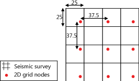
Schematic example of incompatible resolutions. After resampling, the output 2D grid will contain nodes which are snapped over large distances (not recommended) click to enlarge
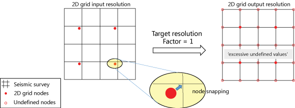
Schematic example of compatible resolutions where the 2D grid resolution is a factor 2 coarser than the seismic survey resolution. The image at the right side illustrates how excessive undefined values are introduced in the output 2D grid when the target resolution has not been defined correctly (factor = 1 is applied, which means that no coarsening of the target resolution has taken place) click to enlarge
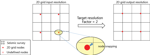
Schematic example of compatible resolutions where the 2D grid resolution is a factor 2 coarser than the seismic survey resolution (same starting point as previous example). The image at the right side illustrates how undefined values in the output 2D grid are avoided when the correct factor is applied to coarsen the target resolution (factor = 2 in this example) click to enlarge