Using trends and projections
With the Trend and Projections form (prepare > Surfaces > Create Surface > Trends and Projections) you can do the following:
- For horizon, unconformity or intrusion output surfaces, apply a trend. This is optional. See Applying a trend (horizons, unconformities, intrusions) below.
- For fault output surfaces, verify and modify (if necessary) the projection normal of the fault plane. See Changing the projection setting (faults) below.
Applying a trend (horizons, unconformities, intrusions)
Trends are useful to 'steer' an output surface at those locations where input data is sparse. Some interpolation algorithms such as IDW and Kriging typically 'flatten out' in those areas, resulting in a horizontal plane further away from input data. By using a trend you have more control over these areas, e.g. to not 'flatten out' to a horizontal plane. Realize that although absolute TVDSS values are not used, the 'absolute' geometry of the trend surface is being used.
You can use a planar trend (trend option 'Planar', see image 1 below) which consists of a flat plane with user-specified dip and orientation. You can also use an existing surface as trend surface (trend option 'From other data', see image 2 below) to follow more complex shapes. Note that input data is always honored, irrespective of the applied trend.
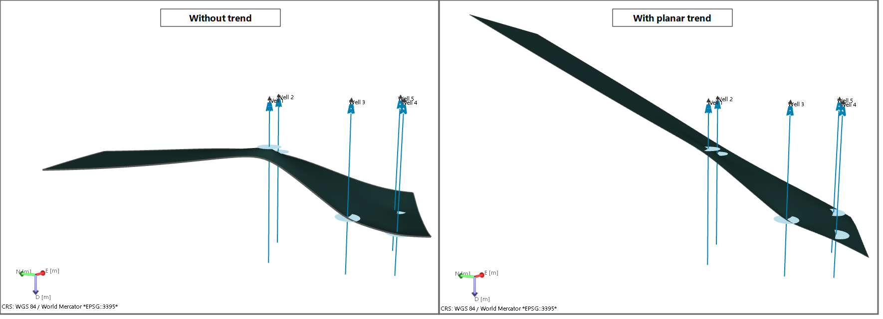
Image 1: Trend option 'planar'. Without a trend, the marker-based output surface (interpolated with IDW) 'flattens out' where there is no marker data (left image). Using a planar, dipping trend surface ensures the output surface sustains its dip beyond marker data (right image). click to enlarge
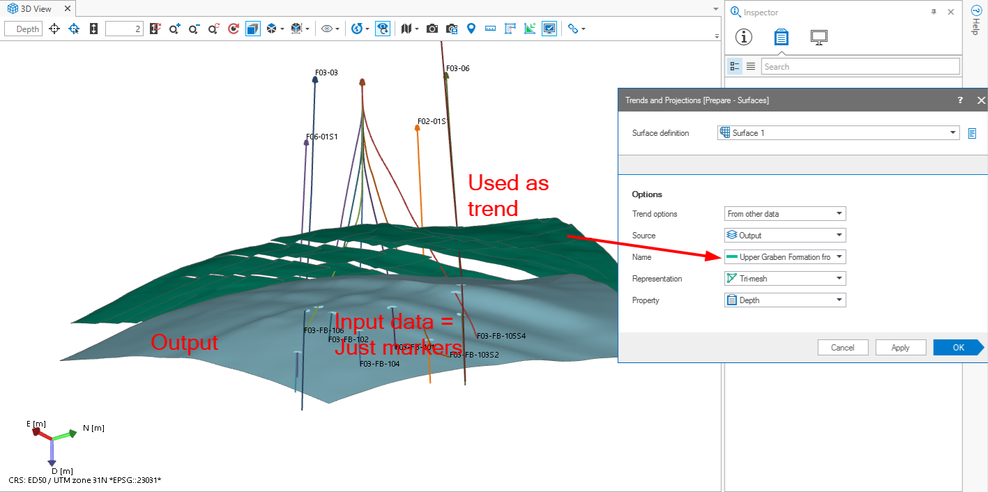
Image 2: Trend option 'from other data'. An existing tri-mesh (dark green) is used as trend to 'steer' the marker-based output surface (in blue). Instead of 'flattening out' the output surface follows the curvature of the trend surface, especially noticeable at the edges. click to enlarge
To apply a trend
- Open the Trends and Projections form.
- At the top of the form, ensure that the relevant surface definition is selected.
- From the Trend options drop-down list, select one of the following:
- Planar - Your trend surface will be a flat plane with specified dip and orientation.
- From other data - You can select an existing surface to be used as trend surface.
- Make sure the trend surface lies at the same geographical location as the input data. In case it is not, the trend surface will be extrapolated (not recommended).
- Ensure that the data density of the trend surface is high (markers as trend surface are therefore not allowed).
- Projection settings from data - The application makes a 'best fitting' plane through the input data. This plane will form the trend surface. Good option when you have sparse data (for example markers) which are indicative of a horizon with more or less constant dip.
- User-defined projection settings - You can manually enter the dip and dip azimuth (GN) of the normal to the trend surface (i.e. enter the direction of the normal):
- Under dip, enter the dip of the normal to the trend surface. For example, if you want your trend surface to dip 30 deg., enter 60 (as the normal to the trend surface dips 90-30=60 deg. in the opposite direction).
- Under dip azimuth (GN), enter the dipping direction of the normal to the trend surface relative to Grid North. For example, if you want your trend surface to dip towards the East (i.e. in the direction of 90 deg.), enter 270 (as the normal of the trend surface dips in the opposite direction, i.e. 90+180=270 deg.).
- Under Source, select the source of the trend surface you want to use. Supported source folders are: Imports folder, Data folder, Surface Sets, Seismic Interpretation.
- Under Name, select the event you want to use as trend surface. All events in the selected source are listed.
- Under Representation, select the representation of the event you selected in the previous step. Supported representation are: tri-mesh, 2D grid, polyline set and point set (markers are not supported).
- Under Property, select the property that describes the trend. Any property with unit 'distance' (m, ft, etc.) can be used.
- When you have finished selecting your trend inputs, click Apply at the base of the form to save the selections and keep the form open, or click OK to save the settings and move to the last workflow step, Construct Surface.
When you use an existing surface as trend surface, note the following:
'Planar'
Select one of the following options:

|
Set from View will use the current orientation of the active 3D View. The normal to the trend surface is formed by the imaginary line between your eye and the displayed object(s) in the view. Rotate your input data in the view until the imaginary line between your eye and the input data bests reflects the normal. A way to do this is to try to spread/distribute the data much as possible over the view. Then click the Set from View button. The dip and dip azimuth (GN) values belonging to the normal are auto-filled on the form. Realize, a dip value of 0 degrees means a vertical trend surface; a dip value of 90 degrees means a horizontal trend surface. |

|
Set to Default will reset the normal to the default values, i.e. dip and dip azimuth (GH) based on input data. This gives the same result as when selecting 'Projection settings from data'. |
'From other data'
Changing the projection setting (faults)
When creating a fault surface, the input data is projected on a 2D plane. The interpolation is performed on this plane, after which the result is projected back onto the original fault plane. By default the plane is auto-calculated based on the input data (radio-button 'Projection settings from data' is auto-selected on the form). In many cases the auto-calculated plane is adequate, but in some cases, for example when the fault curves strongly or in multiple directions, the auto-calculated plane is not optimal. In this case you have to select the radio-button 'User defined projection settings' and define this plane yourself. Note that you do not enter the dip and azimuth of the plane itself, but of the normal to the plane which is called the projection vector.
To change the default projection to user-defined
- At the top of the form, ensure the relevant surface definition is selected.
-
Select User-defined projection settings, which enables the dip and dip azimuth (GN) entry fields.
- Under dip, enter the dip of the normal to the projection plane. For example, if you want the projection plane dip 30 degrees, enter -60 (as the normal to the plane is (30-90)= -60 degrees). Note that it is irrelevant which direction you choose for the normal, i.e. 'inward' (towards the data) or 'outward' (away from the data) as long as you both the dip value and dip azimuth (GN) value are according to the same system.
- Under dip azimuth (GN), enter the dipping direction of the projection plane relative to Grid North. For example, if you want the projection plane to dip in north-western direction, enter 315 degrees.
- Optionally use one of the following buttons:
- When you have finished the projection settings, click Apply at the base of the form to save the settings and keep the form open, or OK to save the settings and proceed to the last workflow step Construct Surface.
|
|
Set from View will use the current orientation of the active 3D View. The normal to the projection plane is formed by the imaginary line between your eye and the fault data in the view. Rotate your input data in the view until the imaginary line between your eye and the input data bests reflects this normal. Then click the Set from View button. The dip and dip azimuth (GN) values belonging to the normal are auto-filled on the form. Realize, a dip value of 0 degrees means a vertical projection plane; a dip value of 90 degrees means a horizontal projection plane. |
|
|
Set to Default will reset the normal to the projection plane to the default values, i.e. dip and dip azimuth (GH) based on input data. This gives the same result as when selecting 'Projection settings from data'. |