Defining observables (reported output)
With the Define Observables form (study > Volumetrics > Volumetric Study > Define Observables) you can specify the contents of your output report. You can specify the volumes to be included, and whether you want to further break-down this volume into smaller 'sub-regions' based on discrete properties you have in your 3D grid(s). You can also define the volume classes (based on cut-off decisions that you made, e.g. GRV, NRV, NPV, etc.) to be included in the report.
To define observables
- Study At the top of the form, select the study of interest.
- Reporting Regions
- Segments
- Zones
- Regions
- Compartments
- Observables Select which volumes you want to include in the report. The terms and variables used in the formulas are explained further below.
- Click Apply and keep the form open, or click Next to proceed to the next step of the workflow, Designs.
In the 'Reporting Regions' section you define the total volume ('Region 1') and volume break-down ('Region 2' and 'Region 3') as follows: at the highest level ('Region 1') you specify the total volume to be included in the report. To select 'Region 1' is mandatory. Optionally, you can further break down this volume into smaller bodies based on discrete properties that you can select under 'Region 2' and 'Region 3'. Note that it is assumed that the selected reporting regions exist for all concepts in the study.
Region 1 (Mandatory) Here you select the total volume to be included in your calculation. You do this via the selection of one of the following property types:
Region 1 defines the total volume, however, it is broken down into smaller bodies of volume, based on the property classes contained by the property type you selected, for example 'Zone-A', 'Zone-B' and 'Zone-C' for property type 'Zone'. When property classes vary amongst assigned 3D grids (for example two 3D grids in two separate volumetric concepts), this is managed by the volumetric report as follows: each 'volumetric concept-property class' combination forms a separate volume in the volumetric report. As an example, if you have four fluid compartments named FC-1, FC-2, FC-3, FC-4 in 3D Grid 1 (Concept A), and only three fluid compartments named FC-1, FC-2, FC-3 in 3D Grid 2 (Concept B), the reported volume is broken down into seven separately reported volumes, namely Concept A FC1, Concept A FC2, Concept A FC3, Concept A FC4, Concept B FC1, Concept B FC2 and Concept B FC3.
For a property type to show up in the drop-down list, it needs to have the same name in all assigned 3D grids (within the volumetric scenario). This is especially important for property type 'region', since you can overwrite its auto-generated name.
When you select the Entire grid as a reporting volume, Region 2 and Region 3 must be set to None.
Region 2 / Region 3 (Optional) Select a discrete property to further break down the reporting volumes you defined under Region 1. You need to specify 'Region 2' before you specify 'Region 3'. You can select from all discrete properties that exist under the 3D grid(s) of your volumetric concepts. If you select a property that does not exist in all assigned 3D grids, the selected property is used in the 3D grid where it exists, and ignored in the 3D grid where it does not exist.
Boundary You can select a boundary (e.g. a lease boundary) as another volume break-down. Volumes will be reported inside and outside the assigned boundary. The boundary needs to be closed (a polygon) and a 'feature' (in the JewelExplorer > Feature Sets folder) to be able to select it (see Working with boundaries and feature sets). You can either import a boundary using the data > Miscellaneous > Geographic Feature button (the boundary will be added to the folder 'Feature Sets' in the JewelExplorer) or you can convert a new/existing polyline set or boundary into a 'feature'. To do this, right-mouse click on the polyline set or boundary and select Create > Create Feature. The newly created featuer is added to the Feature Sets folder in the JewelExplorer and can be selected from the Boundary drop-down list on the form.
| Observable | Abbreviation | At reservoir conditions | At stock tank (surface) conditions | Formula |
|---|---|---|---|---|
|
Bulk Volume |
BV |
✔ |
[Vcell] |
|
|
Net Volume |
NV |
✔ |
BV * [ntg] |
|
|
Pore Volume |
PV |
✔ |
NV * [ɸ] |
|
|
Water Pore Volume |
WPV (Pore volume occupied by water) |
✔ |
PV – ( Oil HCPV + Gas HCPV ) |
|
|
Gas Hydrocarbon Pore Volume |
Gas HCPV (Pore volume occupied by gas) |
✔ |
PV * [Sg] |
|
|
Oil Hydrocarbon Pore Volume |
Oil HCPV (Pore volume occupied by oil) |
✔ |
PV * [So] |
|
|
Gross Rock Volume |
GRV* |
✔ |
[Vcellabove FWL] |
|
|
Net Rock Volume |
NRV* |
✔ |
GRV * [ntg] |
|
|
Net Pore Volume |
NPV* |
✔ |
NRV * [ɸ] |
|
|
Free gas |
Amount of gas originating from the gas phase in the reservoir |
✔ |
Gas HCPV / [Bg] |
|
|
Solution Gas |
Amount of gas originating from the oil phase in the reservoir |
✔ |
Free Oil * [Rs] |
|
|
Free Oil |
Amount of oil originating from the oil phase in the reservoir |
✔ |
Oil HCPV / [Bo] |
|
|
Condensed Oil |
Amount of oil originating from the gas phase in the reservoir |
✔ |
Free Gas * [Rv] |
|
|
Free Water |
Total amount of water in the reservoir |
✔ |
WPV / [Bw] |
|
|
Total Hydrocarbon Pore Volume |
Total pore volume occupied by hydrocarbons |
✔ |
PV * [So] + PV * [Sg] |
|
|
Total Oil |
Amount of oil originating from oil phase and gas phase |
✔ |
Oil HCPV / [Bo] + Free Gas * [Rv] |
|
|
Total Gas |
Total amount of free gas, solution gas and adsorbed gas |
✔ |
Gas HCPV / [Bg] + Free Oil * [Rs] + Adsorbed gas |
|
|
Total BOE in place** |
Total amount of oil and gas in barrels of oil equivalent |
✔ |
[Total Gas / 5800 scf/boe] + Total Oil |
|
| Average NtG bulk | ✔ | NV/BV | ||
| Average NtG pay | ✔ | NRV/GRV | ||
| Average pore bulk | ✔ | PV/NV | ||
| Average pore pay | ✔ | NPV/NRV | ||
| Average Sw | ✔ | |||
|
* Please be aware that the calculations for these volumes depend on the Fluid Leg Definition. ** You can change the value of conversion factor, on the Constants form, which is used to calculate the Total gas in BOE. The default value is 5800 scf/boe. |
||||
Explanation of terms and variables used in the formulas:
|
Vcell |
Total grid cell volume |
|
Vcellabove FWL* |
Total grid cell volume above FWL |
|
Vcelloil leg* |
Total grid cell volume in oil leg |
|
Vcellgas leg* |
Total grid cell volume in gas leg |
|
ntg |
Net to gross ratio |
|
ɸ |
Porosity |
|
So |
Oil saturation |
|
Sg |
Gas saturation |
|
Bo |
Oil formation volume factor |
|
Bg |
Gas formation volume factor |
|
Rs |
Solution gas-oil ratio |
|
Rv |
Vaporized oil-gas ratio |
|
* Please be aware that the definitions of these volumes depend on the Fluid Leg Definition. |
|
Graphical explanation of some of the terms:
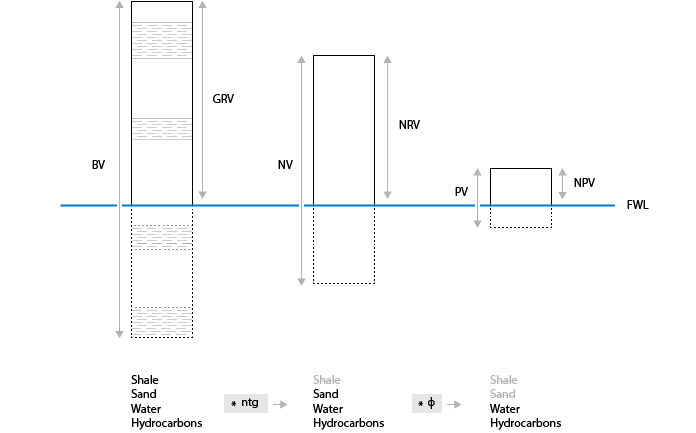
Terms used for reported volumes: GRV, NRV and NPV take into account only the volumes above the FWL, whereas BV, NV and PV take into account the entire grid. In any case only the volumes within the defined regions are calculated. click to enlarge