3D View toolbar
The toolbar at the top of every 3D View contains a set of tools to customize the view and make it easier for you to inspect your data.
|
|
Show Z-axis quantity Displays information about the Z-axis
|
||||||||||||

|
Set focus to point Set the focal point. Click the icon and then click an area or object in the model that you want to become the new focal point for viewing. The new focal point will be centered in the view. The model will pivot around the new focal point when the model is rotated. To return the focal point to the center of the model, click the reset icon  . .
|
||||||||||||
|
|
Set focus to object Reset the view so that the center of an object becomes the focal point. Click the icon and then click an object in the 3D View or in the JewelExplorer. The center of the selected object is the new focal point. The new focal point is centered in the view. To return the focal point to the center of the model, click the reset icon .
|
||||||||||||

|
Scale in Z-axis direction Scale only in the vertical direction for a more detailed view. Enter a value for depth/area scale ratio in the box next to the icon. | ||||||||||||
|
|
Reset Z-axis scale Clear all vertical scaling changes to the view. This sets the depth/area scale ratio back to 1. | ||||||||||||

|
Zoom in Incrementally zoom in. | ||||||||||||

|
Zoom out Incrementally zoom out. | ||||||||||||
|
|
Reset zoom Clear all zoom changes. | ||||||||||||
|
|
Reset zoom, rotate, scale and pan Clear all view changes and reset the view. Press Alt to switch between the user-defined and auto-calculated view box. The user-defined view box can be set with Set focus to object, see above. | ||||||||||||
|
|
Perspective or orthogonal view Change the display between perspective and orthogonal view. |
||||||||||||
|
|
View from View your model from different directions.
|
||||||||||||
|
|
Clipping box Use a clipping box.
|
||||||||||||
|
|
Visuals Various visual options.
|
||||||||||||
|
|
Rotate Change the rotation mode in your 3D View.
|
||||||||||||
|
|
Show detailed model while transforming If the 3D View shows a very large amount of data, you can speed up the refreshing rate when rotating or zooming by toggling this option on. Model details, such as well names or object colors, are hidden while the model display is being changed. When the option is toggled on, all details remain shown during the display transformation. |
||||||||||||
|
|
Cross section Various options to create planar or vertical cross section.
|
||||||||||||

|
Snapshot to Clipboard Copies the current view to the Clipboard for usage in other applications. | ||||||||||||

|
Snapshot to file Saves the current view to file, file-name and destination are user-defined. | ||||||||||||
|
|
Probe (shortcut key: Ctrl+I) Tool that displays information for the location that the cursor is hovering over or pointing at. In the 3D view, when turned on, you can view the name of the object and the 3D coordinates of the location that the cursor is pointing at. This information is displayed both in the Status Bar and in a text box that appears in the view just below and to the right of the cursor. In the Well View, when turned on, you can view the depth and log value of the position that the cursor is pointing at. | ||||||||||||
|
|
Measurement line Measure the distance between two points. Select the tool and click at two points. The distance between the points, apparent dip and azimuth are shown in the 3D View. Display the Output Info pane to also view the locations of each point as well as lateral distance and vertical distance. | ||||||||||||
|
|
Measurement polygon Measure the area of a polygon. Select the tool and click at multiple points in your 3D View. A line is drawn between the last clicked point and the first clicked point to complete a polygon. The distances between each apex of the polygon are shown in the 3D View along with the area enclosed by the polygon. The area is displayed as a yellow highlighted surface. Display the Output Info pane to also view the locations of each point as well as the total length of the perimeter. |
||||||||||||
|
|
Measurement triangle Similar to the previous measurement tool, but uses only three points. Select the tool and click at three points in your 3D View to complete a triangle. The following information is shown in your 3D View: the area of this triangle, the distances of each side, the dip and azimuth of the single plan defined by the three corner points. Display the Output Info pane to also view the locations of each point as well as the total length of the perimeter. |
||||||||||||
|
|
Multisample Anti-Aliasing When turned on improves the display quality by smoothing out the stair step lines and jagged edges. You can change the 'MSAA number of samples' setting in the View Inspector of a 3D View. Higher values result in better display quality but slower rendering, and vice versa. |
||||||||||||
|
|
View linking Various options to link multiple views. See View linking options for more info.
|


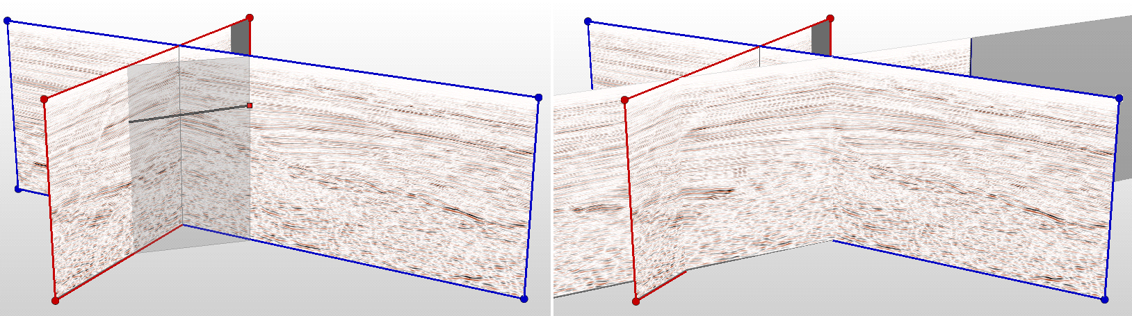
Creating an arbitrary cross section click to enlarge