Intersection quality
Building a 3D Mesh for the purpose of Finite Element simulation requires as set of tri-mesh surfaces as input which need to fulfill special requirements. The model needs to be 'boxed-up' to provide a contained volume. The tri-meshes are used to subdivide the modeling volume into element sets and to steer the re-meshing to obtain a certain resolution. For these purposes, the contacts between tri-meshes need to be 'associated'. This means that every boundary node that contacts another tri-mesh surface needs to have a matching node on the latter ('node pairs'). This requirement is stricter than the watertight requirement (see Definition of watertight and associated surfaces).
You can use the Intersection Quality test of the Diagnostic Tool in the 3D mesh structural strip for a visual inspection of your model. All tri-mesh boundaries are tested for their contacts to other tri-meshes in your 3D mesh structural model. The color scheme of highlighted nodes is as follows:
- Watertight: Yellow
- Free: Orange
- Associated: Blue
- Mixed: Red
- Undefined: White (should never happen)
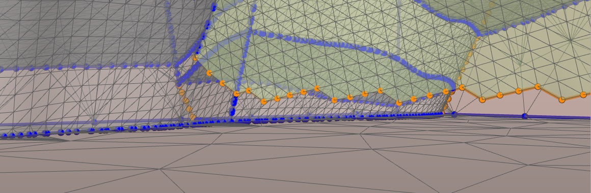
Example in which the tool identified a free boundary section, highlighted in orange. click to enlarge
Watertight contacts that are shown in yellow depict contacts that do not necessarily generate a hole. However, the yellow rendering marks sections where there is no match between nodes of the two, or three touching surfaces. For this, the strict requirement of “associated” contacts is not fulfilled. In the case of a watertight but not associated node you can either run the Associate Surfaces (model > 3D Mesh > Structure Builder) again, or match the node directly. To match a node, select the marked node and move it onto its corresponding counterpart on the other surface using the Move Node tool. Use the option Snap to node to make sure that the node location is matched.
Holes at e.g. horizon/fault contacts need to be closed. The holes can be identified by looking for free nodes (orange) sections along apparent intersection boundaries. When a hole is encountered, you have to fix the issue by running the Associate Surfaces (model > 3D Mesh > Structure Builder) again.
Solving the issue using the (editing) tools
You can either extend the surface or you can close small holes by adding individual triangles. Make sure that you move newly introduced nodes onto the corresponding nodes of the other surface (“snap to node”) to establish the associated state.
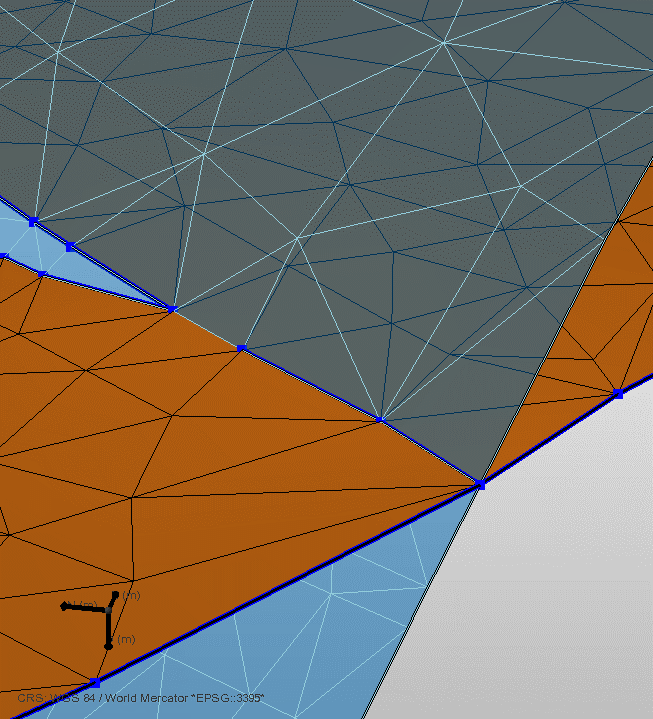
Same image as above. After node-snapping the contact is associated and well resolved, and depicted by blue nodes and segments. click to enlarge
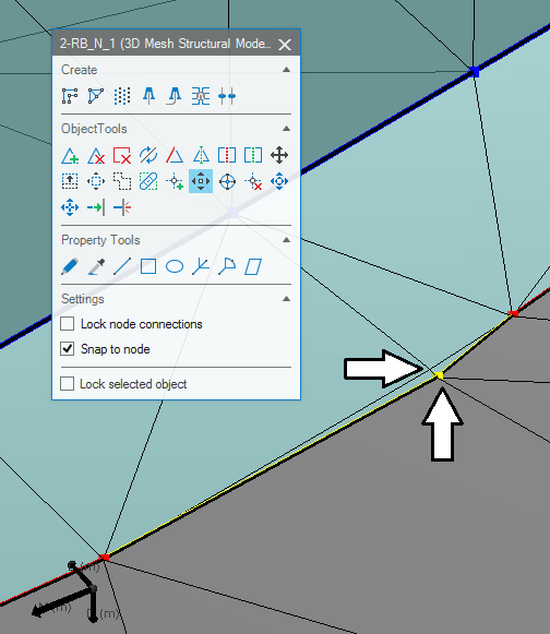
Example of a watertight node marked in yellow. Here you can use the Move Node tool using the Snap to node option to move the node onto the corresponding node of the blue surface. Check that the triangle edges need to match up. click to enlarge