About tartan patterns
A tartan pattern is a design of straight lines at varying distances and crossing at right angles. A tartan pattern is used to create a 3D tartan grid in which cell size is variable in both lateral directions. The X and Y axes of the pattern represent the directions parallel to and perpendicular to the planes of hydraulic (and natural) fractures. Close to the fractures grid cells are small, going outward they get larger. The Tartan view is a 2D view that allows you to inspect and edit the grid cell size distribution in the lateral directions. (The grid cell size in a 3D tartan grid in the vertical direction is defined by the applied source 3D grid.)
On the Fracture Definition form (SIMULATE > Hydraulic Fractures > Fracture Definition) you specify, among other parameters, the fracture density, position and orientation. In the Tartan view you try various tartan patterns and see which coarsening factors, both perpendicular and parallel to the fracture planes, give the best result.
On the Tartan Grid form (SIMULATE > Hydraulic Fractures > Tartan Grid), the grid coarsening parameters appear as well and are synchronized with the settings in the Tartan view.
When you first open a Tartan view, the left pane shows a tartan pattern based on natural fractures. The hydraulic fractures are displayed after you have clicked Apply or OK on the Fracture Definition form (see image). On the right in the Tartan view, you can modify the fracture and grid patterns using the available controls. Switch the display of unrelated objects off in JewelExplorer.
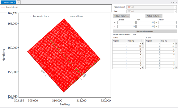
Example of a Tartan view. Hydraulic fractures and natural fractures are shown click to enlarge
How to modify the tartan design
You can modify the tartan design using the controls at the right side of the Tartan view. At the top are two inaccessible fields that show the name of the currently active Fracture model and Area. You set both on the Fracture Definition form. You can change the tartan pattern by changing the hydraulic fracture parameters (in the Hydraulic Fracture view, as shown in the ‘Hydraulic fractures’ section below), the natural fracture parameters (in the Natural Fracture view) or the Cell size parameters in the Tartan view.
Hydraulic fractures
To open a Hydraulic Fracture view, click Hydraulic fractures at the top right in your Tartan view. This window shows all settings stored in the selected Fracture Definition, such as fracture locations, direction and properties. Inspect the data and edit if necessary. You can, for example, change the location of fractures and create a fracture pattern with irregular spacing.
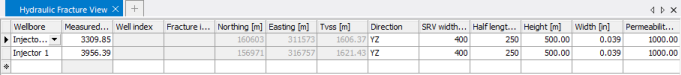
Hydraulic Fracture view click to enlarge
Cell size parameters
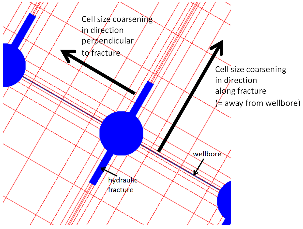
The Cell size, Max and Factor fields in the Tartan view allow you to edit the parameters that control the cell size increase in the grid: the minimum and maximum grid cell size in the direction perpendicular to and in the direction parallel to fracture planes, and the coarsening factor away from fractures.
Cell size click to enlarge
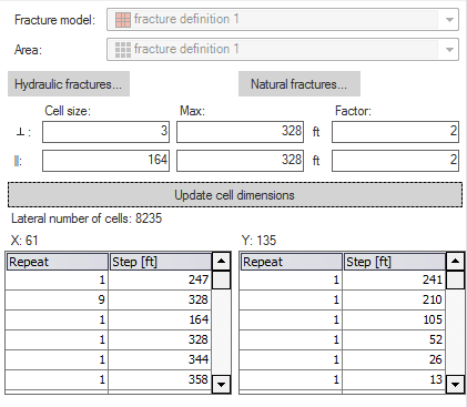
Editing parameters in a Tartan view click to enlarge
Cell size Grid cell size at the fracture in the direction perpendicular to (˔) or along (ll) the fracture; this setting applies to hydraulic fractures and natural (not deactivated) fractures.
Max Maximum grid cell size in the direction perpendicular to (˔) or along (ll) the fracture; this setting applies to hydraulic fractures and natural (not deactivated) fractures.
Factor Multiplication factor for grid cell size increase.
Update cell dimensions Click to update the Tartan view. You do not have to click Apply or OK on the form, since changing these settings does not change the Fracture definition.
The table below the Fracture/ Min/Max/Factor fields shows the result of the tartan settings in terms of grid cell distribution along the X and Y axes. You cannot edit this table.
Repeat Number of grid cells with a certain size (step) along the X and Y direction.
Step Grid cell size.
Natural fractures
Natural fractures can also contribute to the flow in the hydraulic fracturing reservoir simulation. They are subdivided into two types: primary and secondary. Primary natural fractures are large natural fractures, supposed to occur as primary sets in the XZ and XY direction. Primary natural fractures have a small total volume compared to volume of the matrix, but a high permeability. Secondary natural fractures are small natural fractures that are opened by the hydraulic fracturing. They have a small total volume compared to the volume of the matrix, and a medium to high permeability. For secondary natural fractures no direction is defined. The secondary natural fractures are not created in the tartan grid as cells. They just contribute to the permeability properties computed on the Tartan Grid Properties form.
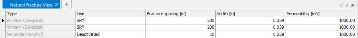
Natural Fracture view click to enlarge
You can set a Fracture spacing, Width and Permeability for the three natural fracture types separately.
The Use column specifies how a specific set of natural fractures contribute to the hydraulic fracture model and to reservoir simulation:
Deactivated If natural fractures of a specific type are deactivated, they are not supposed to be a factor in the reservoir stimulation. The fractures do not contribute to the tartan design, there is no cell size coarsening away from these natural fractures. In reservoir simulation, no fracture porosity or permeability is taken into account for deactivated fractures.
SRV Natural fractures of the selected type within the Stimulated Reservoir Volume are supposed to be open, or be opened due to the fracturing. The fractures are included in the tartan design. Grid cell size coarsens away from these natural fractures in the Stimulated Reservoir Volume, but not in the model area outside the SRV. In reservoir simulation, the fracture porosity or permeability is taken into account.
Full field All natural fractures of the selected type in the fracture model area are supposed to be open, or be opened due to the fracturing. The fractures are included in the tartan design. Grid cell size coarsens away from these natural fractures in the entire fracture model area. In reservoir simulation, the fracture porosity or permeability is taken into account.
When you change spacing or the use of the natural fractures, the Tartan view updates automatically.