Working with boundaries and feature sets
Within the JewelSuite Subsurface Modeling application, there are multiple forms where you select a boundary. Depending on where you are in the application, this requires a different type of input.
Option 1 - The boundary that you select on the form is a polyline set, the type is set to 'Boundary' in the Inspector (see image below). These boundaries are stored in the JewelExplorer, in the Data > Boundaries folder. Boundaries of this type can consist of a single or multiple, open or closed polylines (this depends on the purpose of the boundary). Boundaries of this type are editable (e.g. they can be used in the Property Calculator) and are the most commonly used boundaries during modeling.
Option 2 - The boundary that you select on the form is a tri-mesh, the surface type is set to 'Mesh Boundary' in the Inspector. These boundaries are stored in the JewelExplorer, inside the Data > Mesh Boundaries folder.
Option 3 - The boundary that you select on the form is a feature. Features are stored in the Geographic Features folder in the JewelExplorer A feature set can contain one or multiple features, but you can only select one feature on the form. Features can consist of one or more open and/or closed polylines or of a point set (you can distinguish the geometry type of a feature in the JewelExplorer by the icon used). It depends on the purpose whether or not a polyline needs to be closed. Using a feature as a boundary (e.g. a lease boundary) is an exception to the more common use of features in the application, see (*) below.
(*) Feature sets in JewelSuite are intended as non-editable data in 2D (although they can have a Z component). They are mostly used as background information (e.g. coastlines, country borders, roads) to aid in making decisions, e.g. you can use features for well pad planning, not as 'input' to modeling steps (the lease boundary as described under Option 3 above is an exception). Most often feature sets are imported, external data. For that reason (and as opposed to polyline sets) feature sets cannot be used in other tools within the application.
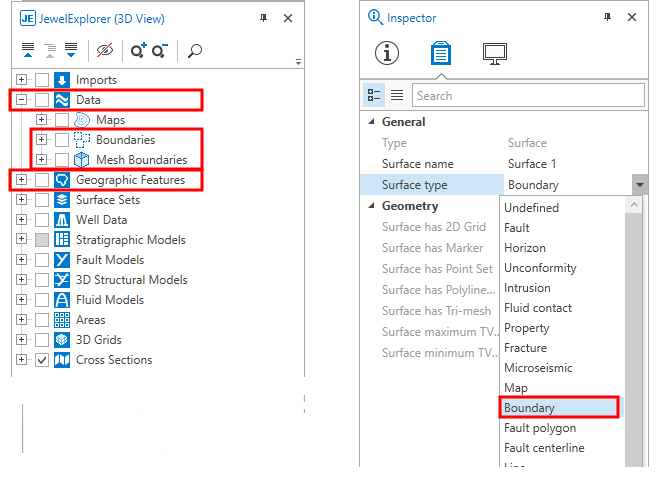
Location of boundaries and geographic features in the JewelExplorer. In the Inspector, make sure that the correct surface type is selected to use a polyline set as a boundary. click to enlarge
The forms act as a filter, and the drop-down lists will only list boundaries of the correct type.
When you need a boundary as a line (i.e. polyline, either open or closed), there are several ways to create one. Once created, polylines are stored in the Data > Boundaries folder as a polyline set (the polyline set will consist of one single polyline in this case). Whether or not a boundary needs to be closed depends on its use. You can verify whether a polyline is closed via the Polyline form (right-mouse click on a polyline set in the JewelExplorer or in a view and select Edit... ). On the form a checkbox next to the polyline's Id marks whether it is closed, or not.
Creating a boundary based on existing data
Right mouse click on a tri-mesh in the JewelExplorer or in the 2D/3D View and select Create > Create Boundary from the context menu.
Right mouse click on a constraint in the JewelExplorer, in the dedicated Thickness/Trend Map View or in the 2D/3D View and select Create > Create Boundary from the context menu.
Right mouse click on an area in the JewelExplorer or in the 2D/3D View and select Create Boundary.
Creating a boundary from scratch
To create a new boundary, click on Data in the JewelExplorer and select Create Object from the context menu. On the Create Object form, type a Name for the boundary you want to create and select Boundary from the Type drop-down list. Click OK to create the boundary and close the form. The new boundary and polyline set representation will appear in the Boundary folder inside the Data folder in the JewelExplorer, but the polyline set will be 'empty' (it does not contain any polylines yet). Next, with the polyline set selected in the JewelExplorer, open the graphical editing tools (Workspace > Tools > Editing Tools). The name of the boundary should appear in the title bar of the floating palette. In your 3D View, make sure you can see a surface on which to 'draw' the boundary. Choose from one of the following scenarios to 'draw' the line:
- Click the Add Polyline icon (W),
 , and click on the surface in your 3D View to define the boundary. It depends on the purpose of the boundary whether or not it needs to be closed (i.e. polygon). In case you need to close it, you can do the following: when you have almost completed the polyline, it will still be open. To close it, select the Close/Unclose Polyline
  tool and click on the polyline you just created. The gap between your first and last points will close up.
 - Click the Add Circle Shaped Polyline icon (L),
 , adjust the settings if needed and click on the surface in your 3D View to define the boundary.
 - Click the Add Rectangle Shaped Polyline icon (K),
 , adjust the settings if needed and click on the surface in your 3D View to define the boundary.
Creating a feature
Right mouse click on a point set in the JewelExplorer or in the 2D/3D View and select Create > Feature.
Right mouse click on a polyline set in the JewelExplorer or in the 2D/3D View and select Create > Feature.
Right mouse click on a wellbore in the JewelExplorer or in the 2D/3D View and select Create > Feature.