Setting the zone thickness to zero by constraining a surface
When you constrain a surface or work with constraint markers, you ‘collapse’ a surface to another surface (above or below) and as a result, the zone in between will receive zero thickness.
There are two different scenarios to constrain a surface. Depending on your data and the model you are building, you choose one of the options:
- Set a zone to zero thickness field wide. To do so, you use the 'Constrain this Surface' option int he Construction Settings column on the Edit Model form in the Structural Modeling workflow.
- Set a zone to zero thickness at a well location using a constraint marker. A constraint marker is an ‘explicit indication’ that a surface does not exist at the well. When you use constraint markers to construct your structural model, you ‘enforce’ that the surface does not exist at the well location(s) and as such that the corresponding zone has zero thickness at that location(s). This can be useful, for example when you model channels. See How to create a constraint marker for more details on how to create a constraint marker.
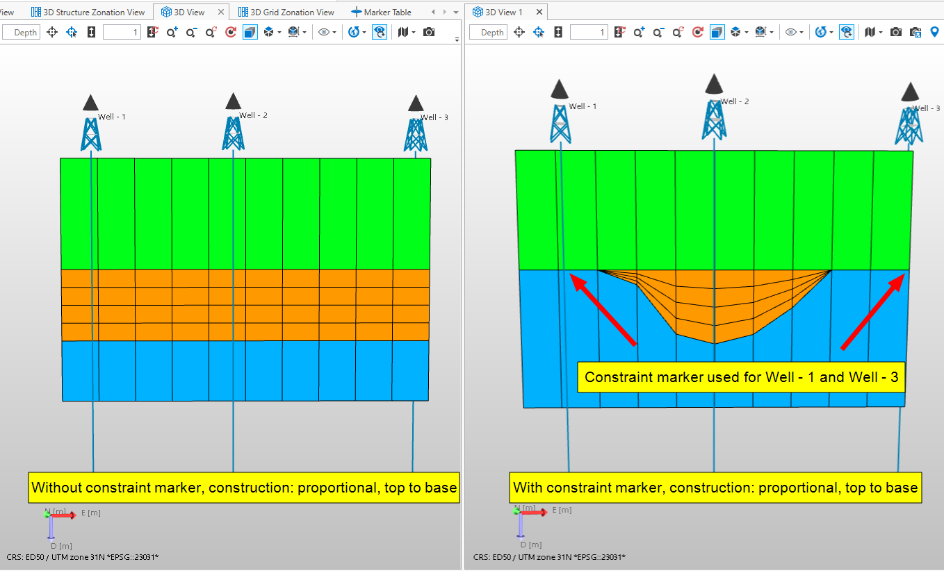
Simplified example showing the difference between creating a grid without and with constraint markers for Well - 1 and Well - 3. click to enlarge
How to create a constraint marker:
- Make sure the Well View is the active view.
- Visualize the wells for which you want to pick the (constraint) marker.
- Open the Editing Tools (Workspace > Tools > Editing Tools)
- Select the Create Marker tool
 . This will open a dialog where you can select a marker set, specify a name and the type of marker.
 - Pick the marker at the desired depth. Start with the well where the marker exists. As soon as you start clicking, the Pick and Move Marker tool
 becomes active.
 - For all the wells where you want the marker to be a constraint marker, hold down the Shift button and then click anywhere along the well.
In the Well View, constraint markers are displayed with a dotted line.
To constrain a surface using constraint markers:
-
In the Well View
If it does not exist yet, create and pick the constraint marker. For vertical wells it does not matter at which depth you pick your constraint marker, because you will constrain the surface to a surface above or below the marker. For horizontal wells the pick location is important for the lateral dimensions. You have to add the constraint marker to the marker set that you will use as input for your structural model.
-
In the Marker Table
Open the Marker Table. In the JewelExplorer, select the marker set that contains the constraint marker to populate the Marker Table. For the constraint markers, go to the following columns and select the correct settings:
Use for modeling Make sure the checkbox is checked for all the markers you want to create a surface for.
Constrain To Select Top or Base. This will be the surface above or below the well marker.
Constraint weight This value is a weight factor and must be between 0 and 1. A 'dummy' constraint marker is generated to determine the smoothness of the surface. If set to 0, the thickness will be set to 0 at the well location of the picked constraint marker. If you increase the value, the point of 0 thickness will be somewhere in between the wells depending on the average thickness of the zone and the weight factor:
depth of the dummy constraint marker = depth of the surface that the marker is constrained to - average thickness of the zone * constraint weight factor.
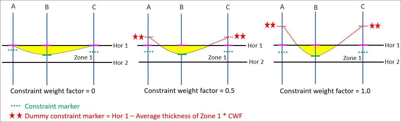
Example showing how the constraint weight factor influences the shape of the surface. click to enlarge
-
In the structural modeling workflow
In the Assign Data step, make sure that you select the marker set that contains the constraint markers. Continue the rest of the workflow.