Discontinuities in the JewelGrid system
Faults
The advantages of the JewelGrid system become apparent when modeling an irregular feature such as a reverse fault, where the same layer can occur twice at the same I, J position. In this case, a purely orthogonal I, J, K grid does not work, because it cannot take into account two grid blocks existing in the same vertical space in the same layer. Some applications have tried to solve this problem by aligning pillars along the fault or collapsing pillars onto the fault. For very complex faulted areas, this solution often fails. The JewelGrid system approaches the same problem in a different way, by splitting the stack of cells into two stacks with the same I, J index. In places where the edges of a stack truncate on a discontinuity, they form an extra stack face where extra depth values can be stored.
In a JewelGrid, a stack of cells can have an indefinite number of stack faces. Each edge of the stack face describes the shape of the face and stores a range of depth values to indicate stratigraphic layering inside the stack. Adjacent stacks can share edges when there is no discontinuity present or they can have separate edges that share the edge geometry but have their own depth values, in case of a dip-slip fault model.
A JewelGrid can model a strike-slip fault by abandoning the standard I, J, K indexation when adjacent stacks face each other across a discontinuity. Instead, extra stack faces and face edges are generated, allowing the faces along a discontinuity to share the same edge geometry. In the diagram, a strike slip fault is depicted between the first and second stack, while a dip-slip fault is depicted between the second and third stack.
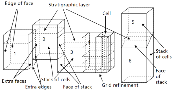
Modeling a strike-slip fault with a JewelGrid. click to enlarge
Local Grid Refinement
The JewelGrid system also allows Local Grid Refinement as shown in the fourth stack of the diagram. Cells and cell stacks can be split into smaller cell stacks whose outer shape is defined by the shape of the original cell stack. The dimensions of the faces that are not shared with the original cell or stack are determined by extra edges with the same features as the original edges. When a discontinuity intersects a number of edges of a cell stack, two cell stacks are created.
Intrusions
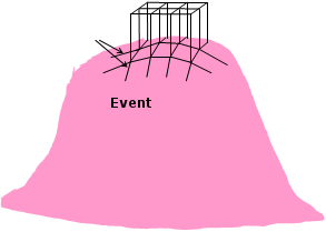
Pillars truncating on an event from event polylines. click to enlarge
Another common modeling challenge is an intrusion such as salt dome. With the JewelGrid system, edges can be truncated on the shape of the dome. The complicating factor in these shapes is two-fold:
- The properties in the intrusion are independent of the properties in the layers being intruded.
- The shape can have multiple occurrences at one lateral location.
You can solve these problems in the JewelGrid system by modeling the intrusion the same way as a (non-faulted) unconformity, i.e. by assigning it to the fault model. This way, the grid cells will be truncated at the intrusion. Note that in order to model the intrusion this way, it needs to be defined field wide. For more on this, see How to model an unconformity.
Erosional events
Erosional events are another important type of discontinuity in reservoir modeling.
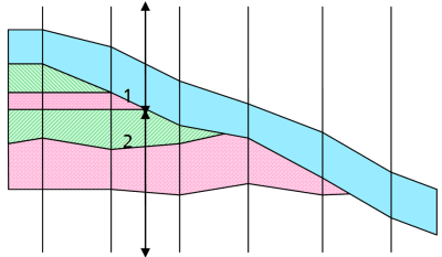
In models using a regular 3D grid, pillars or edges have to be aligned with faults so that it is nearly impossible to align the pillars with an erosional event. As a result, the erosional event has to be modeled as a layer, whose depth values are stored in the regular pillars or edges. This means that layers have to be modeled across the field and pinched out at the pillars or edges. While this could have an undesired effect, regular 3D grids leave no other choice.
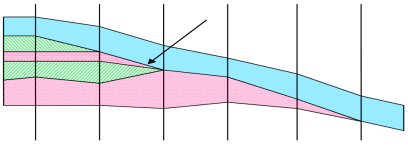
Problems modeling erosional events using regular grids (1). The pinch-out is always restricted to the boundary of a cell. click to enlarge
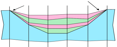
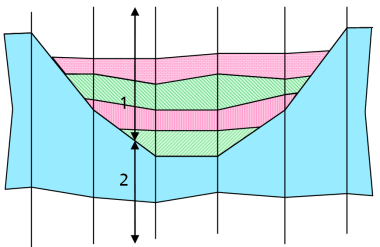
Problems modeling erosional events using regular grids (2). The pinch-out is always restricted to the boundary of a cell. click to enlarge
The JewelGrid system allows you to model the erosion as a discontinuity instead. On how to do this, see How to model an unconformity.
Modeling an erosional event as a discontinuity using the JewelGrid system (1). Here the pinch-out of individual layers can be independent of the location of the cell boundaries click to enlarge
Modeling an erosional event as a discontinuity using the JewelGrid system (2) click to enlarge