Faults and NNCs view
This view is opened upon clicking Edit faults on the Faults and NNCs form. Fault descriptions are taken from the faults in the associated 3D grid model and added to the simulation case with the Connect faults option on the Faults and NNCs form or with the Update from model option of the 'Master table' context menu (see below).
Tables on the 'Faults and NNCs view'
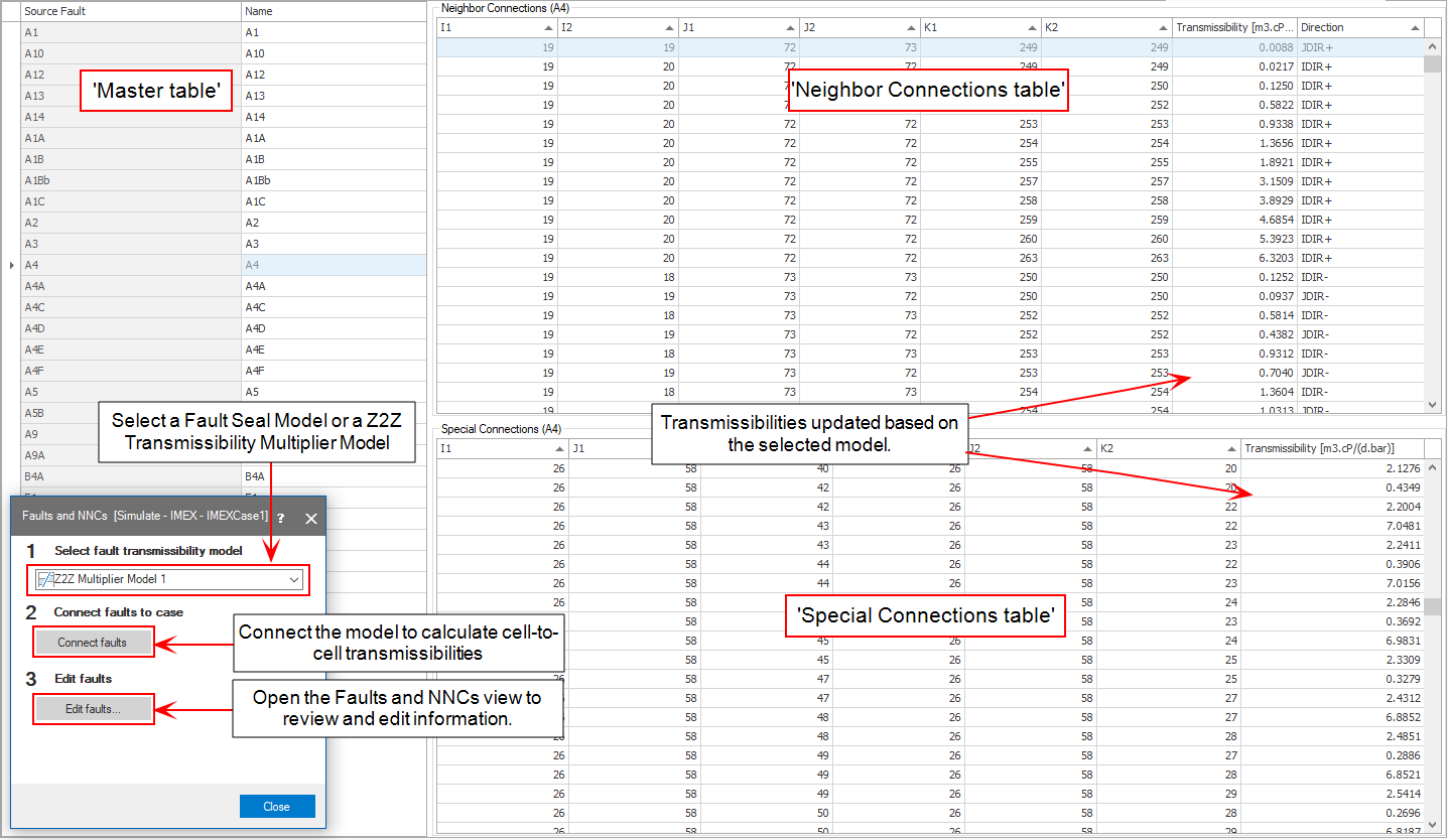
The Faults and NNCs view displays three tables, the 'Master table', the 'Neighbor Connections' table and the 'Special Connections' table (indicated in the images under 'Option 1' and 'Option 2' further below). The upper-left table is the 'Master table' via which you control the other tables.
'Master table' with faults and JewelGrid NNCs This table (located at the upper-left side of the view) lists all the faults connected to the simulation case. If you have checked the option to Enable fault threshold pressure on the Faults and NNCs form, then a third column is added to the master table to enter the threshold pressure value per fault. Depending on the selection you make in this table (either a fault or the lowermost row 'JewelGrid NNCs'), the 'Neighbor Connections' table and 'Special Connections' table are updated.
When you select a fault in the 'Master table':
The 'Neighbor Connections' table shows the neighbor connections across the selected fault. The cell indices of the schematic grid determine if cells are logical neighbors. For cells to be logical neighbors, the index values for two directions (e.g. SimI and SimJ) have to be equal, and in the other direction (e.g. SimK) the difference should be exactly one.
The 'Special Connections' table shows the non-neighbor connections across the selected fault. In other words, this table lists all the connections between cells that are in contact in the JewelGrid but not in the schematic grid. This is due to mapping of the cells to additional k-layers, see Reservoir simulation using a JewelGrid. See image A below.
When you select JewelGrid NNCs in the 'Master table':
The 'Special Connections' table shows all the non-neighbor connections of the simulation case, i.e. connections between cells which were initially in contact in the JewelGrid, but due to the mapping to additional k-layers in the schematic grid, they are no longer in contact (i.e. JewelGrid connections which got broken, see image B below).
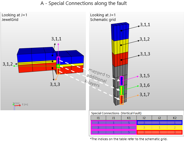
Image A - Image demonstrating special connections along the fault (connections of cells cut by the fault in the JewelGrid). For example, the 'hanging wall' part of cell 3,1,1 in the JewelGrid, which is mapped to the schematic grid (as cell 3,1,5) has special connections with cell 3,1,1, cell 3,1,2 and cell 3,1,3. You can display these special connections in the 'Special connections' table by selecting the relevant fault in the 'Master table'. click to enlarge
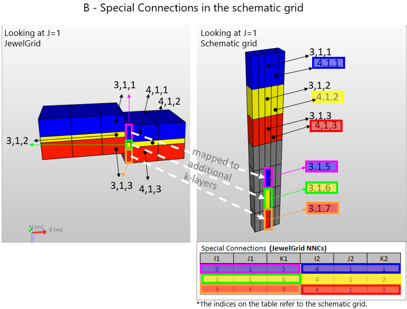
Image B - Image demonstrating special connections due to mapping to the schematic grid. For example, the 'hanging wall' part of cell 3,1,1 in the JewelGrid, which is mapped to the schematic grid (as cell 3,1,5) has a special connection with cell 4,1,1 in the JewelGrid. You can display these special connections in the 'Special connections' table by selecting the lowermost row (called 'JewelGrid NNCs') in the 'Master table'. click to enlarge
'Master table' (upper-left table in the view, listing all the faults)
- Source fault Name of fault in the 3D grid to which the fault is connected.
- Name Name of the fault in the simulation case. Used internally within the application. Not generated in the deck.
'Master table' context menu options
Select one or multiple cells in the 'Master table', then right-mouse click on a cell to have the following options:
- Copy cells / paste cells Copy and/or paste a selection of cell values from/to the table, for example from/to Microsoft Excel™ spreadsheet.
- Clear cells This will delete the content from the cell (not valid for the Source Fault column).
- Cancel selection Deselects the selection.
Right-mouse click anywhere in the table to have the following options:
- Clear all faults This will empty the 'Master table' and associated Neighbor Connections and Special Connections tables.
- Update from model Imports/connects to the faults in the 3D grid (same as Connect faults option on the 'Faults and NNCs' form).
Neighbor connections table
- I1, I2, J1, J2, K1, K2 Grid cell range for the fault surface.
- Transmissibility Transmissibility of the neighbor connection.
- Direction Direction of the transmissibility.
Special (non-neighbor) connections table
- I1, J1, K1 Grid indices of the 1st cell.
- I2, J2, K2 Grid indices of the 2nd cell.
- Transmissibility Transmissibility for the connection between the 1st and 2nd cell.
Applying connection or fault transmissibility multipliers
The application provides two ways to modify/determine cross-fault transmissibility in the simulation input. By assigning a Fault Seal Model or Zone to Zone Transmissibility Multiplier Model to your simulation case with the Faults and NNCs form. For more information, see the options below.
You can use a Fault Seal Model to add fault transmissibility, stored in the model, as a third component to the cell to cell transmissibility. You can create a Fault Seal Model with the Fault Seal Modeling workflow of the model > Fault Seal strip. Using a Fault Seal Model is the recommended way to determine fault transmissibility, see the Fault Seal Modeling workflow.
To use a Fault Seal Model, select it on the Faults and NNCs form (see inset in image further below), then click Connect faults. At that moment, the cell to cell transmissibility values in the tables of the view are updated and reflect the final cell to cell transmissibility (CTRtot). The calculation is as follows:

where:
CTRtot = Total transmissibility (m3)
CTRno fault = Cell to cell transmissibility (m3)
FTM = Fault transmissibility multiplier (unitless) - stored in the Fault Seal Model
Tf = Fault transmissibility (m3) - stored in the Fault Seal Model
When you are using a Fault Seal Model and click Connect faults, three QC properties, representing CTRno fault, CTRtot and their ratio CTRtot / CTRno fault are generated in the JewelExplorer under the surface sets folder with the name <3D Grid> - <Fault Seal Model>. They are stored under the same point set as where the Fault Seal Model properties are stored (see Fault Seal Modeling) with the following names:
- <simulation case name> - FSM - CTR with FSM (= CTRtot)
- <simulation case name> - FSM - CTR without FSM (= CTRno fault)
- <simulation case name> - FSM - CTR Ratio (= CTRtot / CTRno fault)
Written behind each property name, between brackets, is the formula term each property represents.
![]() Option 2 - By using a Zone to Zone Transmissibility Multiplier Model
Option 2 - By using a Zone to Zone Transmissibility Multiplier Model
You can use a Z2Z Transmissibility Multiplier Model to apply fault transmissibility multipliers to the cell to cell transmissibilities. You can create such model with the Zone to Zone Transmissibility Multipliers workflow of the model > Fault Seal strip. A Z2Z Multiplier Model allows you to specify transmissibility multipliers per zone to zone connection (Z2ZTM in the formula below). This way the lithological characteristics of the (stratigraphic) zones (as they are juxta-posed across the fault) can be translated into reduced transmissibility for each cross-fault grid cell connection. Next to this, you can specify a fault transmissibility multiplier per fault (FTM in the formula below). Both Z2ZTM and FTM are stored in the Z2Z Multiplier Model.
To use a Z2Z Multiplier Model, select it on the Faults and NNCs form (see inset in image below), then click Connect faults. At that moment the cell to cell transmissibility values in the tables of the view are updated and reflect the final cell to cell transmissibility (CTRtot) values. The calculation is as follows:

where:
CTRtot = Total transmissibility (m3)
Z2ZTM = Zone to zone transmissibility multiplier (unitless) - stored in the Z2Z Multiplier Model
FTM = Fault transmissibility multiplier (unitless) - stored in the Z2Z Multiplier Model
CTRno fault = Cell to cell transmissibility (m3)
While (re-)assigning a Fault Seal Model or a Zone to Zone Transmissibility Multiplier model, make sure to always click Connect faults on the Faults and NNCs form, each time you update that model.
Assigning a Fault Seal Model or Z2Z Transmissibility Multiplier Model (generated with the model > Fault Seal strip) to your simulation case. click to enlarge
Transmissibilities in the simulation deck
In JewelSuite Subsurface Modeling, there are two types of connections across a fault:
- neighbor connections across the fault
- non-neighbor connections across the fault
If the Fault Seal Model or Z2Z Transmissibility Multiplier Model results in zero transmissibility values for a cross-fault connection, the faults and NNCs tables become empty.
The number of neighbor and non-neighbor connections affected by the Z2Z Transmissibility Multiplier Model or Fault Seal Model depends on the merging rules set for the SimGrid on the 'Reservoir Description' form. A non-neighbor connection across a fault might disappear due to merging. When you select a model for your simulation case, its effect will be reflected on the connections of the unmerged simulation grid. If any of the cell merging options is selected on the Reservoir Description form, the cell merging algorithms take care of the resultant transmissibility values.
For CMG simulators (IMEX™, GEM™ and STARS™) JewelSuite Subsurface Modeling provides all connections (both neighbor and special) via the IRCONNECT keyword. IRCONNECT keyword allows the user to specify irregular inter-block connection data. In this way, information is provided via geometry and CMG uses its internal transmissibility calculation to calculate fluid flow and additionally to calculate heat convection and conduction for STARS™ thermal simulator.
In the IMEX™/GEM™/STARS™ simulation decks:
-
Modifications on the special connections across the fault are reflected via the TRANSF keyword.
-
Modifications on the neighbor connections across the fault are also reflected via the TRANSF keyword.
In the ECLIPSE™/tNavigator™ simulation decks:
-
Modifications on the special connections across the fault are reflected under the NNC keyword.
-
Modifications on the neighbor connections across the fault are reflected with the TRANX, -Y, -Z keywords.