Lateral extent of the Structural Model and 3D Grid
When you create a Structural Model and 3D Grid with the Structural Modeling and 3D Gridding workflows respectively, several factors determine the lateral extent (i.e. the 'edge') of the output models, in other words, how far the (horizon) surfaces will be constructed laterally and the lateral number of grid cells in the 3D Grid. It is therefore important to understand these factors, so that you can make your modeling decisions accordingly. Examples of factors influencing the edge are the extent of the input data and any assigned 'Boundary' or 'Area'.
The next paragraphs give an overview of all factors determining the model's edge, and how these factors interrelate. Also the lateral extent of the QC grid (auto-generated during surface construction) is presented. As the Structural Model is input to the 3D Grid, both models are discussed separately.
Lateral extent of the Structural Model
During the 'construct surfaces' step of the Structural Modeling workflow (model > 3D Structure > Construct Surfaces), horizon surfaces are laterally constructed up to a certain perimeter, i.e. the model's edge. The position of this edge, which defines the lateral extent of the Structural Model, depends on the following three factors:
- Input data extent meaning the smallest enveloping rectangle around all horizon input data, including markers
- Use of a boundary (option on the Create Boundary form of the Structural Modeling workflow)
- An unconformity assigned to the fault model (an unconformity which is not assigned to the fault model will be modeled in a similar way as a 'normal' input horizon, see About unconformities and intrusions).
Only without the use of a boundary and without an unconformity assigned to the fault model, will the lateral extent of the Structural Model be determined by the extent of the input data. Once a boundary or an unconformity assigned to the fault model are used, they determine the lateral extent of the Structural Model. When both a boundary and unconformity assigned to the fault model are used at the same time, there are some nuances. The sections below discuss these four possible scenarios:
![]() Scenario 1 - Only input data (no boundary used, no unconformity assigned to the fault model)
Scenario 1 - Only input data (no boundary used, no unconformity assigned to the fault model)
In this scenario, the lateral extent of the horizon input data determines the lateral extent of the constructed surfaces and as such, the lateral extent of the output Structural Model. The lateral extent of the Structural Model is the smallest enveloping rectangle around all horizon input data, including markers. This is visualized in the image below, where the input marker lies outside the area occupied by the input surface.
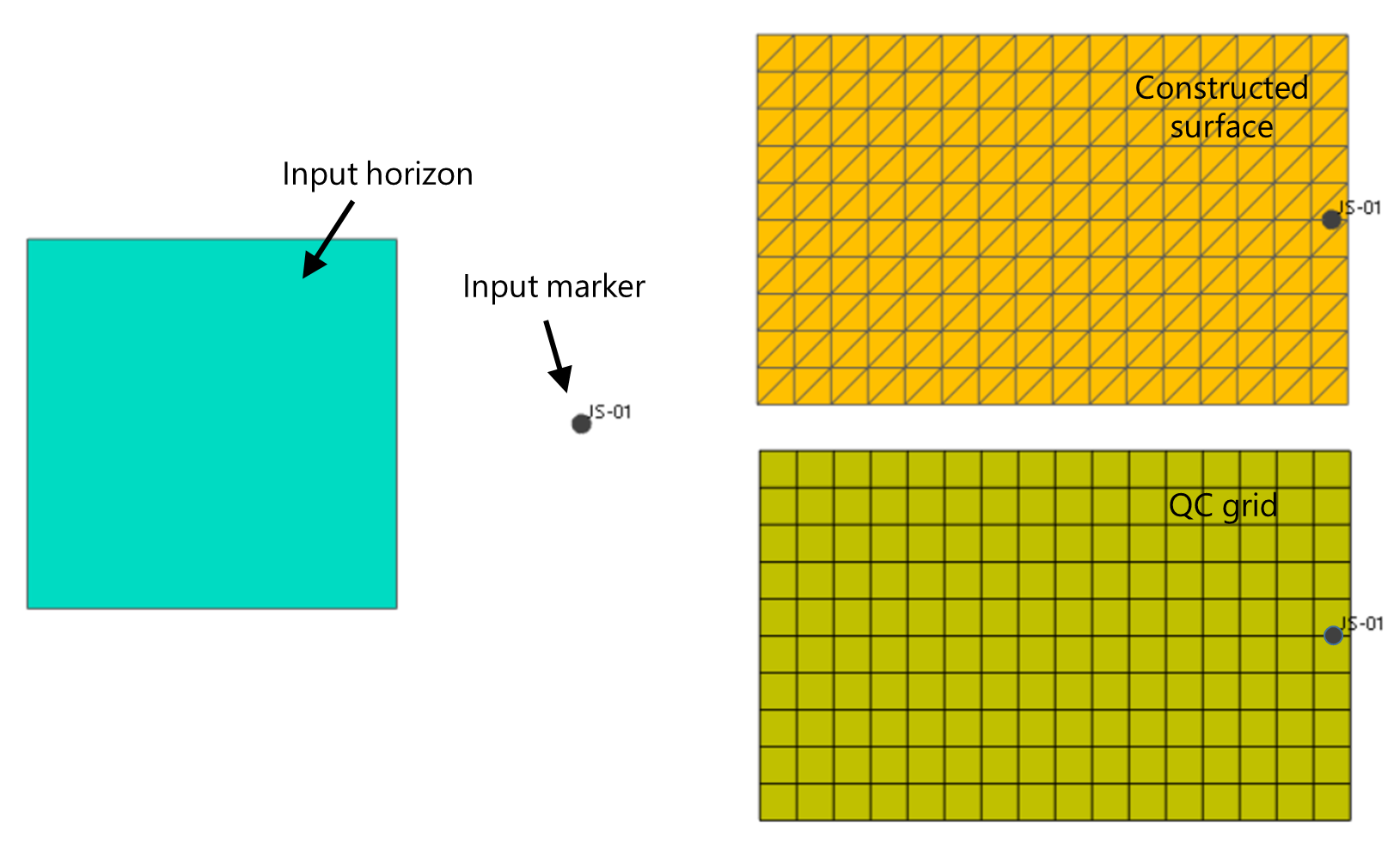
Example of how the Structural Model's edge is determined when no boundary is used and when no unconformity is assigned to the fault model. Surfaces are constructed (upper-right image) over the smallest rectangle enveloping all input data, including markers (see marker outside the horizon area in the left image). The QC grid (lower-right image) is ever consistent with the Structural Model's lateral extent. click to enlarge
![]() Scenario 2 - Boundary used, no unconformity assigned to the fault model
Scenario 2 - Boundary used, no unconformity assigned to the fault model
If you use a boundary (option on the Create Boundary form of the Structural Modeling workflow), the edge of the structural model is formed by this boundary and the surfaces will be constructed up to this boundary (see image below).
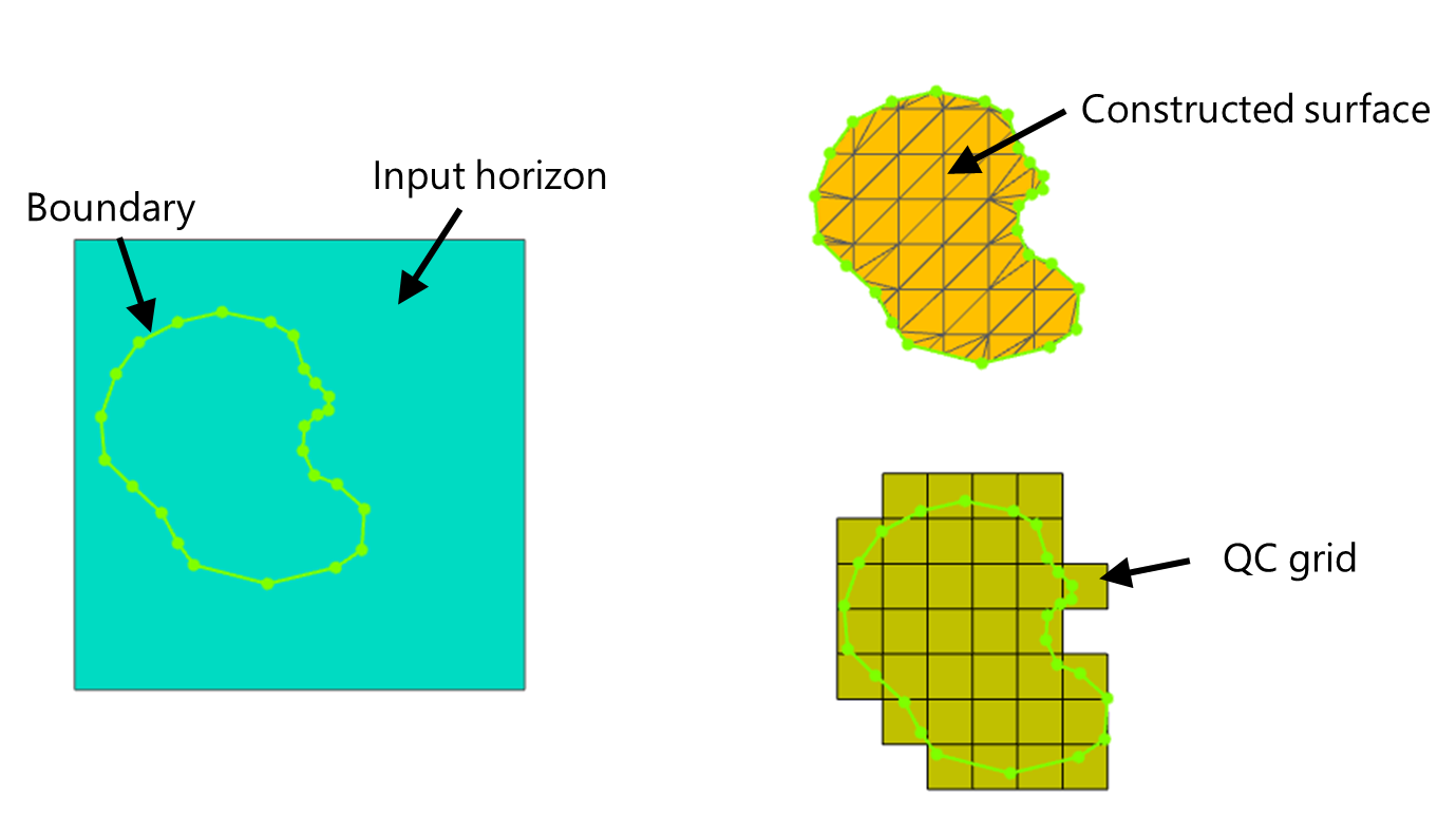
Example of the effect of using a boundary on the lateral extent of the Structural Model. The input horizon (left image) is 'clipped' at the boundary (upper-right image). The QC grid (lower-right image) is ever consistent with the Structural Model's lateral extent. click to enlarge
![]() Scenario 3 - No boundary used, unconformity assigned to the fault model
Scenario 3 - No boundary used, unconformity assigned to the fault model
When you have an unconformity assigned to the fault model, surfaces will be constructed over the area where the unconformity exists, irrespective of the input data extent. In other words, the edge of the Structural Model will follow the edge of the unconformity.
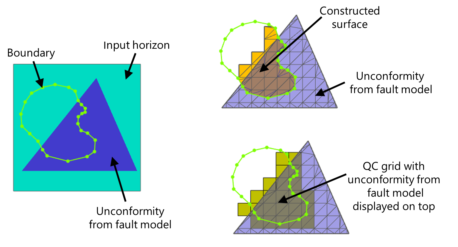
- In case the lateral extent of the unconformity assigned to the fault model is less than that of the (other) input data (see images below, upper image), the constructed surfaces will be 'clipped' at the unconformity's edge. You can avoid this by making the unconformity as lateral extensive as the other input data (see About unconformities and intrusions).
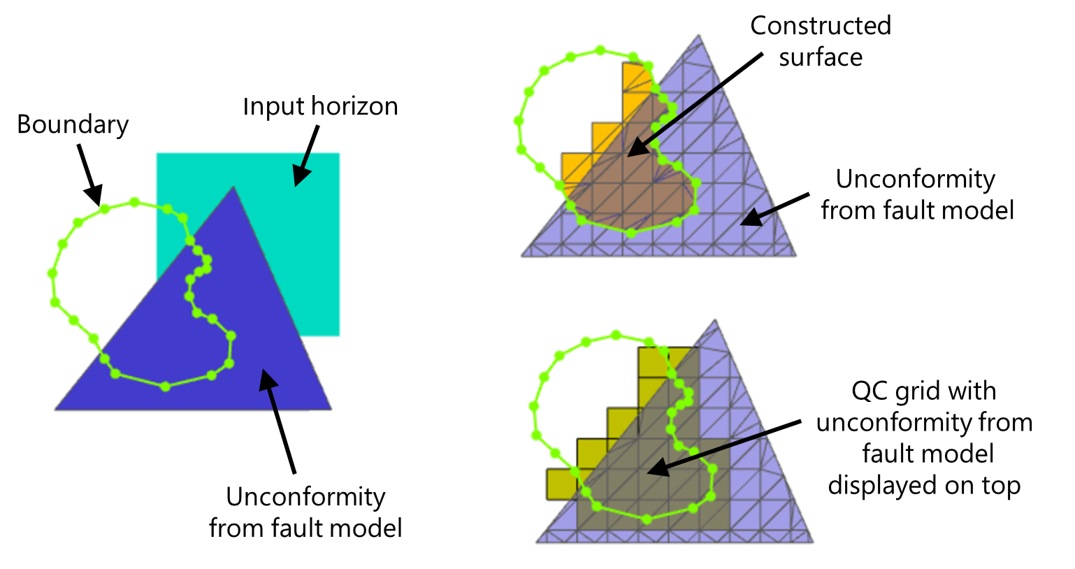
- In case the unconformity assigned to the fault model extends beyond the input data (see images below, lower image), the constructed surfaces will be extrapolated up to the unconformity's edge.
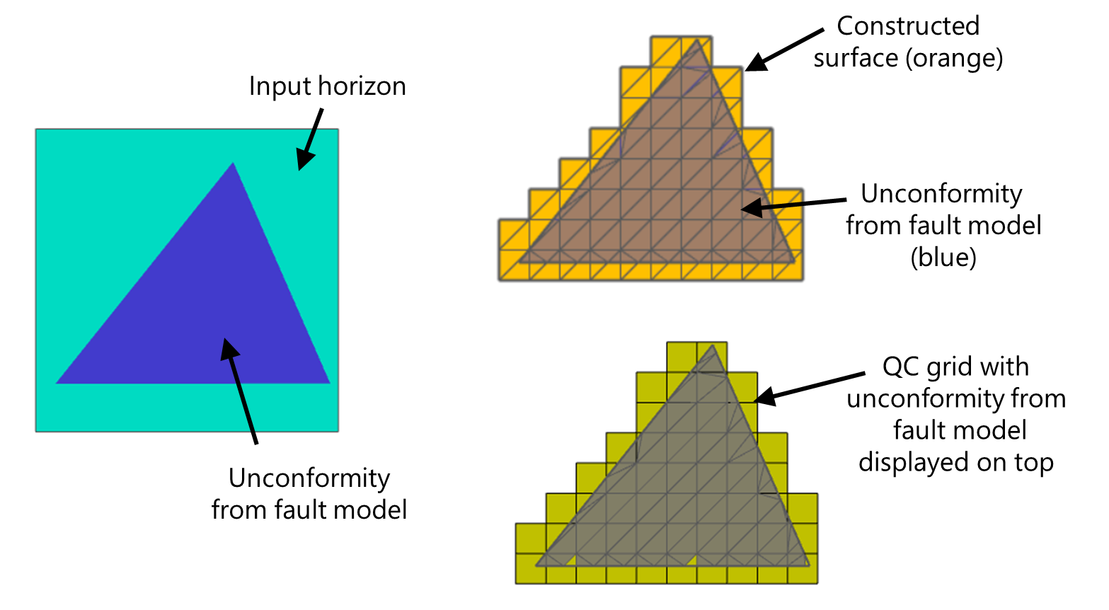
The size of the unconformity (assigned to the fault model) is more dominant than the input data extent. The lateral extent of the Structural Model (orange surface, upper-right image) follows the lateral extent of the unconformity, even though the input data (left image) is 'more extensive' than the unconformity. The QC grid (lower-right image) is ever consistent with the Structural Model's lateral extent. click to enlarge
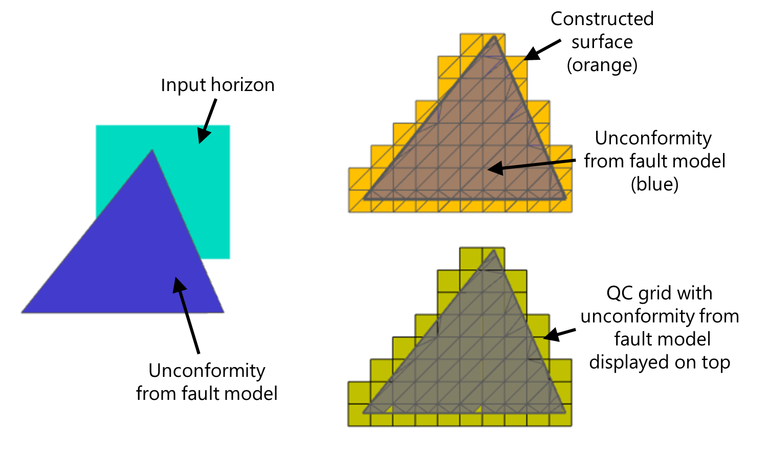
The size of the unconformity (assigned to the fault model) is more dominant than the input data extent. The lateral extent of the Structural Model (orange surface, upper-right image) follows the lateral extent of the unconformity, even though the input data (left image) is 'less extensive' than the unconformity. The QC grid (lower-right image) is ever consistent with the Structural Model's lateral extent. click to enlarge
![]() Scenario 4 - Boundary used and unconformity assigned to the fault model
Scenario 4 - Boundary used and unconformity assigned to the fault model
In this scenario, both a boundary and an unconformity assigned to the fault model are used during construction of the Structural Model. Both are limiting factors to its lateral extent. Similar to Scenario 2, surfaces will be constructed within the boundary, however, only where the unconformity exists. In other words, when both a boundary and unconformity are part of the structural model, surfaces will be constructed where the area within the boundary and the area covered by the unconformity, coexist. This is irrespective of the input data extent (see both images below with different lateral extent of the 'Input horizon'). Note that the boundary 'smooth cuts' the edge of the constructed surface.
Example of a combination of a boundary and an unconformity assigned to the fault model affecting the lateral extent of the Structural Model. Surfaces are constructed where the area within the boundary and the area covered by the unconformity coexist (orange surface, upper-right image). This is dominant over the input data extent (compare with image below). The QC grid (lower-right image) is ever consistent with the Structural Model's lateral extent. click to enlarge
Example of how the combination of a boundary and an unconformity assigned to the fault model affects the lateral extent of the Structural Model. Surfaces are constructed where the area within the boundary and the area covered by the unconformity coexist (orange surface, upper-right image). This is dominant over the input data extent (compare with the previous image). The QC grid (lower-right image) is ever consistent with the Structural Model's lateral extent. click to enlarge
Lateral extent of the 3D Grid
The same principles that determine the lateral extent of the Structural Model apply to the lateral extent of the 3D Grid (model > 3D Grid > Construct 3D Grid). This means that the three factors which control the lateral extent of the Structural Model as described above, namely the input data extent (now the Structural Model extent), the use of a boundary (now the boundary on the 3D Grid > Assign Area form) and the 'unconformity assigned to the fault model' (now the unconformity in the Structural Model) control the lateral extent of the output 3D Grid in the same way. The only difference is that when the input data determines the lateral extent, for the Structural Model this is the smallest enveloping rectangle (around the input data) while the lateral extent of the 3D Grid is irregular.
An extra and very important constraining factor is formed by the Area. The Area is a mandatory selection on the Assign Area form of the 3D Gridding workflow, and the Area always constrains the lateral extent of the 3D Grid. See the image below, where the lateral extent of the 3D Grid follows the lateral extent of the input data (i.e. the constructed surfaces of the input Structural Model) but is ultimately cropped by the Area.
The lateral extent of the 3D Grid can be summarized as follows:
- Structural Model extent + Area: The 3D Grid exists where both overlap (note that the edge of the 3D Grid is irregular and not, like in the Structural Model, an enveloping rectangle).
- (Boundary and/or Unconformity from the fault model) + Area: The 3D Grid exists where the boundary, the unconformity originating from the fault model and the Area overlap (note that the Structural Model extent has no influence once a boundary or unconformity are used).
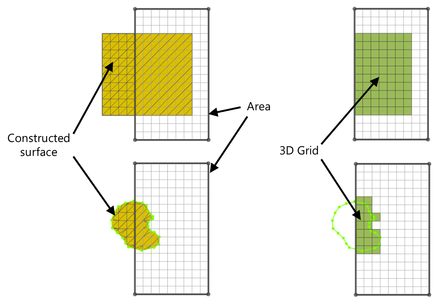
In creating the 3D Grid (images on the right), the Area crops the outline of the input Structural Model (images on the left). click to enlarge
Using the boundary on the Assign Area form (3D Gridding workflow)
The 'Assign Area' form of the 3D Gridding workflow contains a 'boundary from' drop-down box. With this option, you can choose to not use a boundary, to use the same boundary as was used during the creation of the input Structural Model, or to use another boundary during the creation of your 3D Grid.
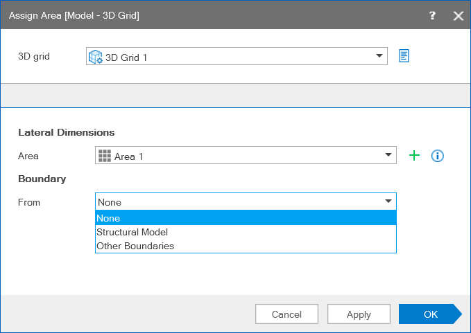
Option to use no boundary, the same boundary as used during creation of the Structural Model, or another boundary during the creation of the 3D Grid. click to enlarge
In case you used a boundary during construction of the Structural Model, it is recommended to select the same boundary here. When you select another boundary, make sure it does not extend (laterally) beyond the edge of your Structural Model. The main purpose of selecting another boundary is to create a 3D Grid over a smaller area ('subset') of the Structural Model.
In case you do not select a boundary, there can be a significant effect on the lateral extent of the 3D Grid, especially when you used a boundary in combination with an unconformity assigned to the fault model during construction of the Structural Model (Scenario 4 above). If you do not select a boundary while constructing the 3D Grid, the 3D Grid will laterally follow the outline of the unconformity (within the Area though). Especially when the unconformity extends beyond the boundary, the effect of not using the boundary during construction of the 3D Grid could be significant (compare the two scenario's below).
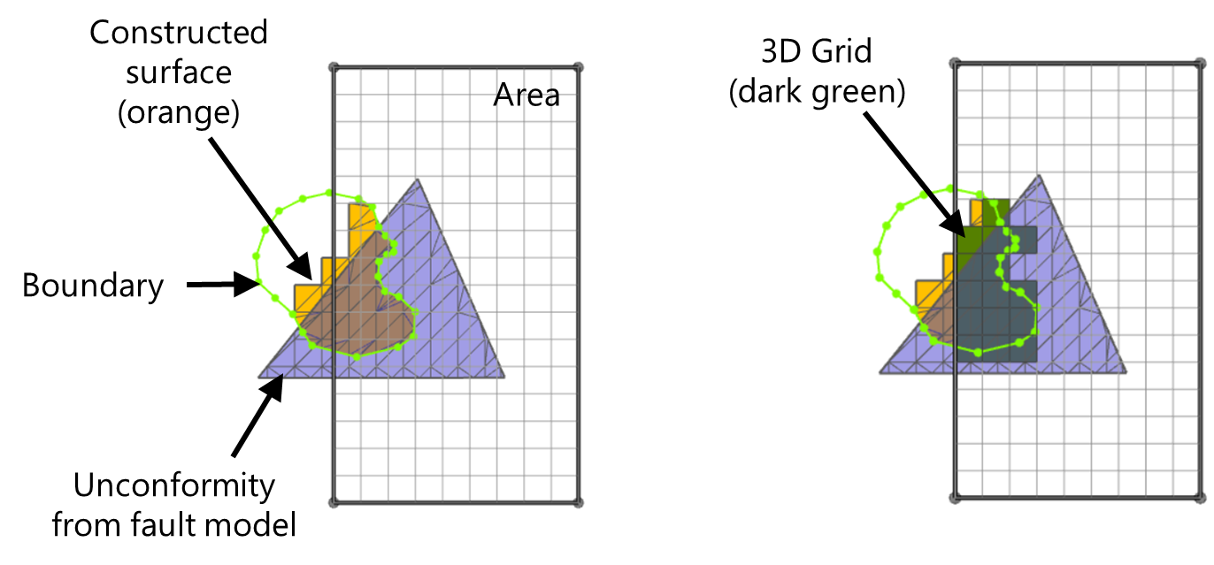
Scenario 1: Boundary from Structural Model selected on Assign Area form. Left image: input to the 3D Grid. Right image: output 3D Grid (dark green). click to enlarge
With the same boundary selected as was used while constructing the Structural Model, the lateral extent of the 3D Grid (dark green in right image) will honor this boundary (within the Area though), and will therefore be in line with the lateral extent of the input Structural Model (orange surface). click to enlarge
click to enlarge
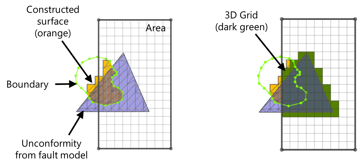
Scenario 2: No boundary selected on the Assign Area form. Left image: input to the 3D Grid. Right image: output 3D Grid (dark green). click to enlarge
With no boundary selected, the lateral extent of the 3D Grid will (within the Area) follow the lateral extent of the unconformity within the Structural Model. click to enlarge