Holes in constructed surfaces or 3D grids
In some cases, you may encounter rectangular holes in constructed surfaces or 3D grids after performing the Structural Modeling and/or 3D Gridding workflows. See the image below, where a hole is visible in the QC grid that was constructed during the Construct Surfaces step in the Structural Modeling workflow. Rectangular holes in the grid typically indicate a flaw in the fault model, which is located in the vertical extent of the hole.
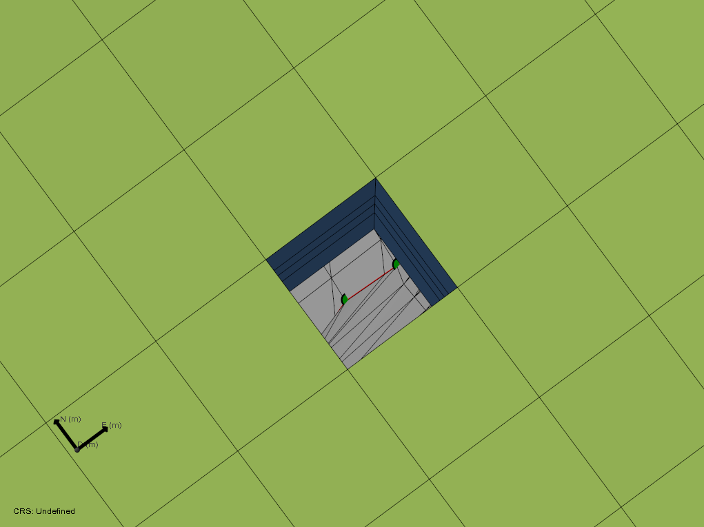
The image shows a ‘vertical’ hole in the QC grid of a 3D structural model. By looking down the hole you can identify the exact location of the problem, which is typically caused by the fault model click to enlarge
Where encountered
- model > 3D Structure > Construct Surfaces / Fault Cutoff Line Edits
- model > 3D Grid > Create Jewel Grid
Cause
When holes in the grid appear during the construction of a 3D grid, it means that the gridder could not resolve a (geometrical) situation introduced by a particular combination of input surfaces and data settings. Since the gridding algorithm is also used in surface construction (during the Construct Surfaces step), holes can also appear in the constructed tri-meshes. Typically, the conflict causing the holes lies in the fault model that is assigned to the 3D structural model, but depending on the exact issue, it can become visible at different stages during modeling:
- Direct problem in the fault model: any 3D structural model or 3D grid using this fault model will have holes.
- Problem that appears in the 3D structural model when additional horizons are added: the issue in the assigned fault model, combined with additional gridding complexity of the additional horizons causes holes in the surfaces.
- Hole that is only visible in the 3D grid: the issue in the fault model only becomes apparent in the 3D grid due to increased gridding complexity, for example the inclusion of k-layers.
Cases where holes in grids occur resulting from issues outside the fault model are rare and will not be discussed here.
How to fix the issue
Step 1: Locate issues
The easiest way to locate issues is to look for holes in the corresponding grid. In the 3D Gridding workflow, these holes are immediately visible in the generated 3D grid. Holes in constructed surfaces, however, are more difficult to locate. A method to more easily locate issues in constructed surfaces is to inspect the QC grid which is generated simultaneously with the 3D structural model.
Once a hole is identified, check (select) the input data in the JewelExplorer and focus the 3D view (see tip in the intro of this topic). Then turn off the 3D grid to identify the location of the issue in the fault model and/or other surfaces.
Step 2: Identify issues in the input surfaces
Geometrical issues that cause gridding problems in a later stage are most commonly caused by faults that are not watertight at locations where watertightness is required, for example
- Small gaps remaining at fault intersections
- Small segments of faults sticking through another fault
- Isolated tri-mesh patches
- Flat or folded triangles
- Tri-meshes in your fault model with very pointy triangles at the intersections
You can locate the flaws in input surfaces by using a grid (as explained in step 1) and subsequently identify the issue by zooming in on the input surfaces at the exact location. This process is visualized in the image below.
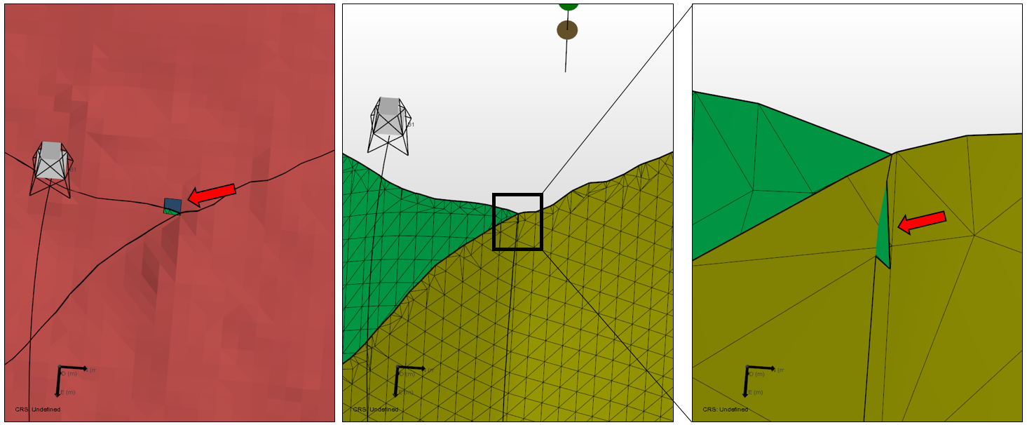
Steps in locating and identifying issues in input surfaces. The hole in the grid marks the location of the issue (left panel). Focus the 3D View on the input surfaces in the hole and switch off the 3D grid (middle panel). After zooming in on the exact location with the input surfaces visualized (right panel), the issue becomes apparent. In this case, a triangle of the green fault is sticking through the yellow fault click to enlarge
Additionally, you can use the Solve Fault Intersections form on the model > Faults strip, which gives the percentage of watertight nodes per intersection. Also, it gives a visual indication of watertight and non-watertight sections (via green dots and dots in the color of the surface, respectively) on the intersection in the 3D view (see image below).
Note that a watertightness smaller than 100% does not mean that gridder issues will always appear; it depends on the location along the intersection. Also, watertightness of 100% does not guarantee no gridding issues will appear, because small non-watertight sections (e.g. beyond the modeling parameters resolution / resolution of the green/white dots) may still be there.
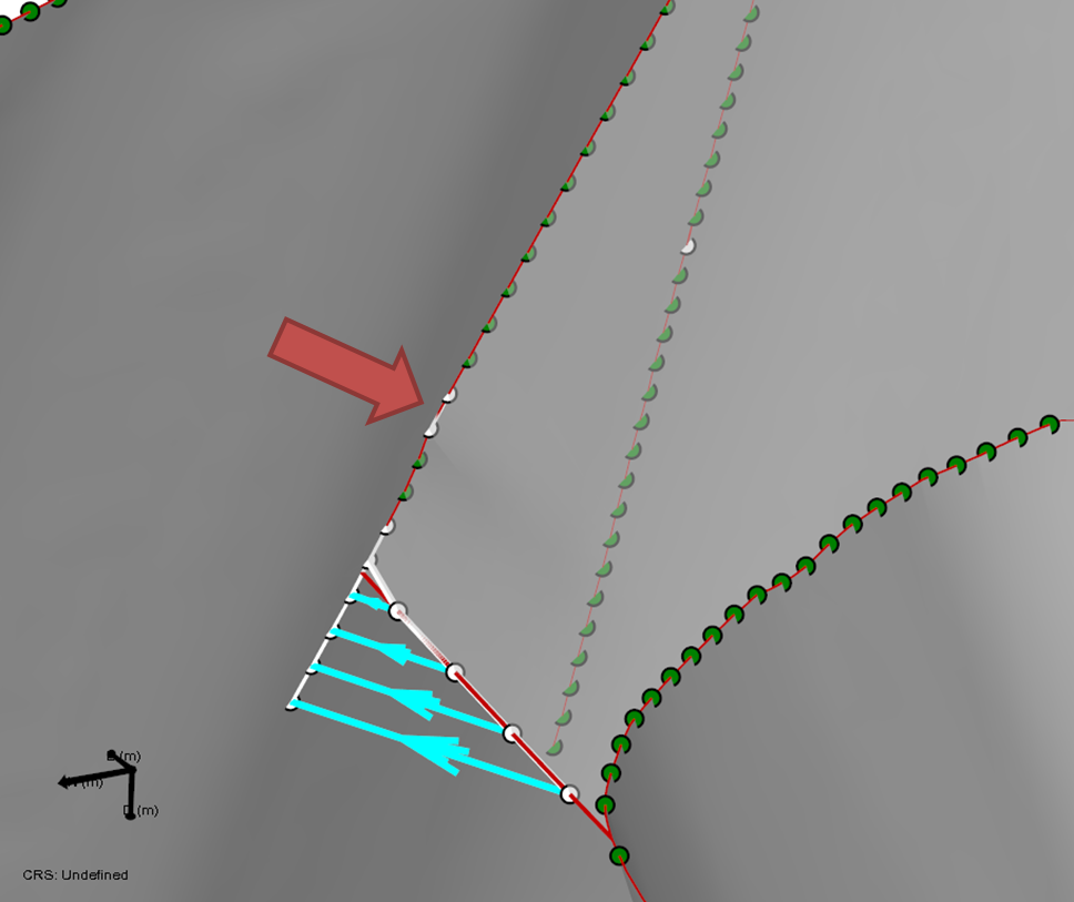
The image shows the results of a fault-fault intersection after applying Solve Fault Intersections: green and white dots indicate watertight and non-watertight sections, respectively. The red arrow indicates a potentially problematic region, where a small hole is present at the location of the white dots. This segment therefore needs additional treatment to prevent issues in the grid. The segment with the blue arrows may be fine: this is a suggested extension that is located at the end of the intersection click to enlarge
Step 3: Fix identified issues
Now that the flaws in the fault surfaces are identified, they need to be fixed.
When fixing the identified issues, first of all you need to make sure that the step Solve Fault Intersections is performed. However, in certain cases, the intersections are not solved successfully, particularly when dealing with tri-meshes that have poor quality triangles (for example elongated slivers). In those cases, a manual interaction is required to clean-up the issues. You can use the following tools:
Structure Builder (model > Faults)
- Retract
- Extend
- Clear intersections
Editing tools for tri-meshes (Tools > Editing Tools)
- Add triangle
- Remove triangle
- Remove triangles under line
- Move node
- Extend tri-mesh
- Retract tri-mesh
- Extend boundary
- Remove triangle patch
Result
After using the various options to clean-up the faults, fault intersections should be watertight where required. To ensure holes in the grid are solved, repeat the gridding process:
- If you edited your faults in the fault model, reassign it to the 3D structural model and perform Construct Surfaces. When finished, inspect the QC grid and ensure the holes in the grid are resolved (recommended option). Afterwards, the 3D grid can be recreated and checked for holes.
- If you edited your faults in the 3D structural model directly (not recommended), you can directly run construct surfaces. Note that the fault model that was used to create the 3D structural model is now out of sync and when using it for other structural models it will again result in holes.
Optional: method to verify fault model compatibility before building the full structural model
In cases with many holes in a grid, or to prevent issues at a later stage, it may be worthwhile to check the compatibility of the fault model with gridding early in the modeling process using a simple structural model. You can do this by performing the following steps (see also image below):
- Create a watertight fault model (see previous steps on how to do this).
- Create a temporary stratigraphic model with only one zone at Level 1, bound by the same top and base surfaces that will be used in the full model later on.
- Create a 3D structural model from the fault model and the temporary stratigraphic model.
- Inspect the generated QC grid for holes. When holes are encountered, inspect the faults at those locations (either the fault tri-meshes or the faults contained in the grid) and resolve the issues.
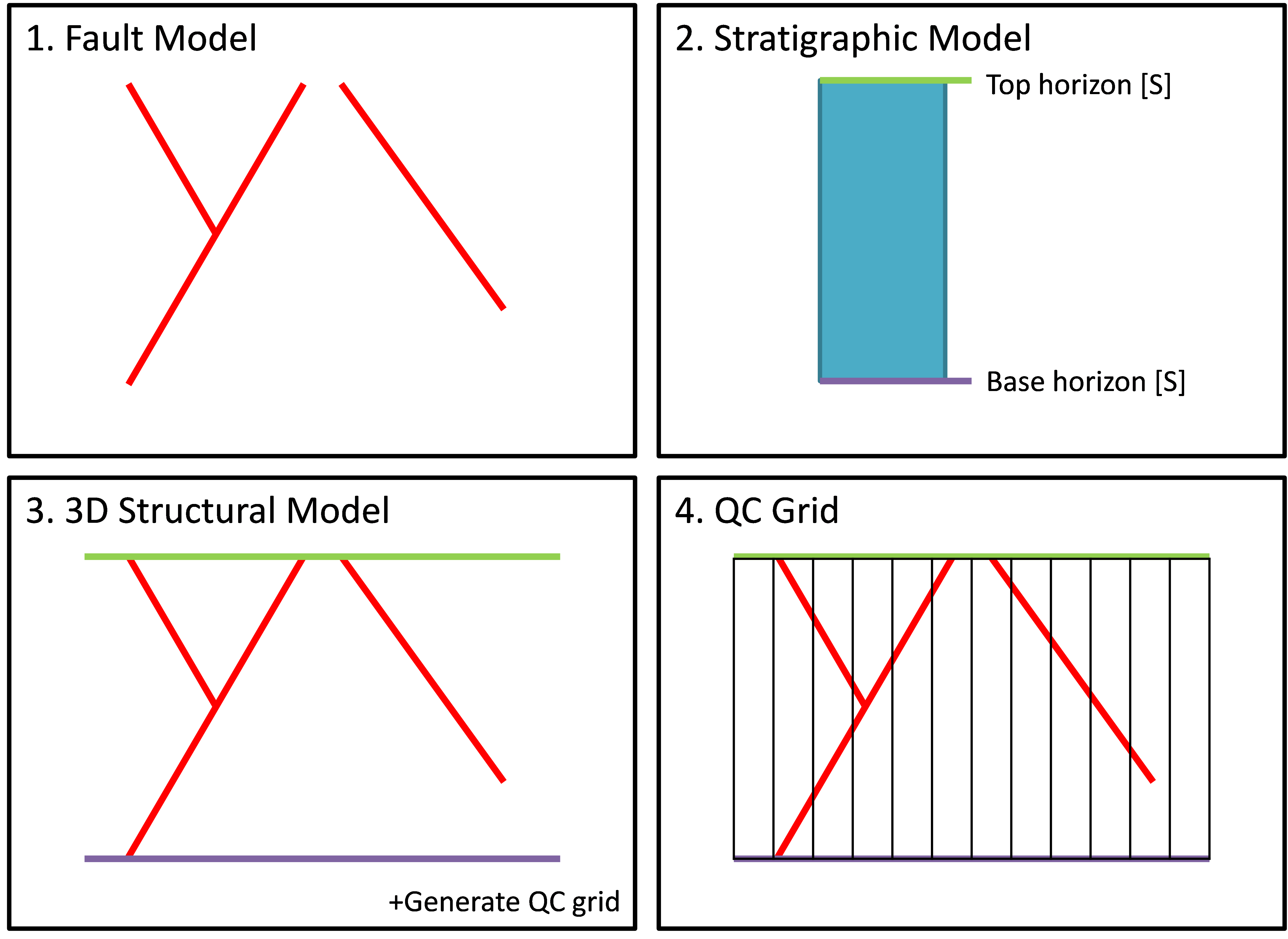
Image illustrating the steps to verify compatibility of a fault model with gridding: (1) create a watertight fault model, (2) create a temporary stratigraphic model with only the top and base horizons, (3) create a structural model including the QC grid and (4) inspect the QC grid for holes click to enlarge