Well schematic display settings
You can define the settings for the well schematic track and its data, such as casing schemes and caliper logs, in the Well View template on the right side of the form, in the Settings pane. These settings also control how the well schematic shows in the Well View.
Track settings
When you click on a track item in the track explorer, the settings related to track display appear in the Settings pane.
Track name A name for the track can be given in this field. The active track item in the track explorer will take the name given here.
Width The display width of the track. The default measurement is pixels (px), however, you can right-click the px designation and choose from centimeters, inches, millimeters or points.
Background Color The background color that will be applied only to the active track.
Gridlines Controls the visibility of gridlines for the selected track.
Grid color If gridlines are turned on you can select their color.
Marker names Controls the visibility of marker names for the selected track.
Align marker names Controls the positioning of the marker names within the track.
Group headers by Displays the headers in a group per log type when selecting Log type and not grouping the headers when selecting None.
Show in header Provides the possibility to display All log names (e.g. GR 1, GR 2, etc.) or Only log type (e.g. GR (2/2)). It might be the case that it is displaying e.g. GR (1/2) if one of the track items is not containing data and the function Show available tracks items was chosen before.
Curve Filling settings
The curve filling settings allow you to customize a fill color and behavior for the logs in a track. You can create fill settings, for example, that fill between track edge and curve, between two curves or between a curve and a value. You can create as many fill settings as desired; these settings can then be managed by arranging the order in which they are applied and by indicating which settings are active.
A toolbar is available for managing your settings, including adding, deleting, and changing the order of the settings:

|
Add a new fill setting to the track. See the Fill Settings table below for details on creating a fill setting for your template. |

|
Change the order in which the settings are applied to the track. To change the position of a specific setting in the order, click the setting to make it active (the setting item will turn blue), then click the up or down arrow to change its position. |

|
Delete the selected setting. To delete a setting, click the setting to make it active (the setting item will turn blue), then click the delete icon. |
Fill settings
When you add a setting to the list with the button in the toolbar, a new, blank setting appears. Here you can specify the fill behavior that will be applied to the curves in the track. The following options are available for each setting:
 The assigned order of the setting. This is read-only. If you wish to adjust the order that the setting is applied, use the arrows as described under Curve Filling Settings above.
 Indicates whether or not the setting is active; checked boxes indicate active settings.
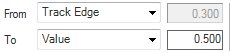
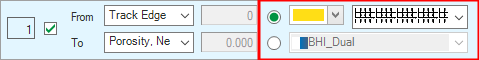
Fill behavior There are a few combinations you can define between the available fill types: Track Edge, Continuous, Value and Mean. Selecting Value activates the adjacent text boxes, where you can specify a value. Selecting Mean will shade the curves from a mean value to the track edge, another mean or log. For normal logs, the arithmetic mean is used. For logarithmic displayed logs, the geometric mean is used.
Fill color Select either a solid color or a colorset to use for the fill setting.
Well schematic settings
In the track explorer, select the well schematic item under the well schematic track. The related settings appear in the Settings pane.
Scale Settings
Mirror scale Controls whether the wellbore diameter (On) or the wellbore radius (Off) is used for the well schematic scale in the Well View.
Manual You can specify minimum and maximum display values for the scale. With Mirror scale On you can only specify the maximum display value. The minimum displayed value is fixed to zero. With Mirror scale Off you can adjust both displayed values.
Automatic Determine the appropriate minimum and maximum values for the scale, based on the wells that are currently displayed in the Well View. You can choose whether the same scale should be applied to all wells or on a well-by-well basis.
Display Settings
Hole size Displays a black line in the track to show the hole outline when On is selected. Select Off to hide the hole outline.
Annulus fill Fills the annulus with a blue color and the hole with a gray color when On is selected. Select Off to hide all filling colors.
Perforations Displays the perforations as short sticks in the schematic track when On is selected. Select Off to hide the perforations in the well schematic track.
Perforation color Select a color to display the perforations (if toggled on) in the well schematic track.
Caliper log Controls whether the caliper log is displayed in the Well View (On) or not (Off). The caliper log is displayed together with the casing scheme in the same track, in the Well View and its scale is automatically adjusted to be the same as the scale of the well schematic. The maximum scale is adjusted to use the highest value between the two data types.
Log A list of caliper logs is available in the drop-down list. Select the log you want to display together with the well schematic in the Well View.
Position Only active when mirror scale is On. The selection here dictates where in the track the caliper log will appear.
Annotations Controls whether log annotations are displayed in the Well View (On) or not (Off).
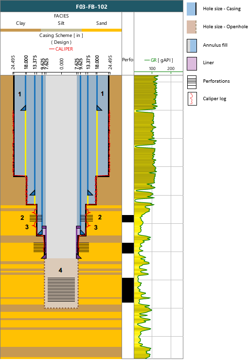
A Well View with a well schematic track and a perforation track. 1 Mirror display of the well schematic track. 2 Display of perforation interval in well schematic track. 3 Mirror display of caliper log together with casing scheme in the same track. 4 Display of perforation interval in open hole (during screen pipe completion). click to enlarge