Defining uncertainty
With the Define Uncertainty form (model > 3D Structure > Define Uncertainty) you select surfaces and intervals to be 'uncertain'. This means their depth and thickness will vary during the probabilistic volumetric calculations with the Volumetrics Study workflow of the study strip. As explained in How depth shifts are calculated, uncertain surfaces and intervals can potentially impact non-uncertain surfaces and intervals in the same sub-sequence. To avoid unintentional shifts of non-uncertain surfaces and intervals you can fix them in place by activating the 'lock' which is located behind each surface and interval in the tables on the form. Locked surfaces and intervals remain in place (and stay unaffected) by shifts of neighboring surfaces or intervals.
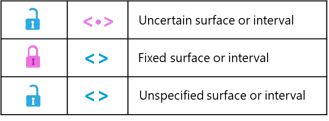
Blue symbols means 'no settings applied', i.e. the surface/interval is not fixed and not uncertain (default settings). Pink symbols mean 'you applied settings'. The pink lock means you 'fixed' the surface/interval; the pink uncertainty symbol means you made the surface/interval 'uncertain'. The lock and uncertainty symbol are mutually exclusive. click to enlarge
Hierarchy of seismic and sub-seismic surfaces and intervals
To help you applying a consistent and meaningful depth and thickness uncertainty strategy, your structural model sequence is divided into two categories, namely 'seismic' and 'sub-seismic' surfaces and intervals (see the two tables on the form). The basis for this distinction lies in the data representations underlying your structural model zonation. 'Seismic' category surfaces and intervals are the ones that are based on 'dense' data representations (i.e. tri-meshes, 2D grids, polyline sets and point sets). 'Sub-seismic' category intervals are the ones based on 'sparse' data representations (i.e. markers and point sets that were manually set to 'sparse' on the Edit Model form > Surfaces tab > checkbox in column 'Point Set is Dense' is unchecked). As such the term 'seismic' is used as a synonym to indicate a wider range of surfaces than only surfaces based on seismic interpretation.
The two tables on the Define Uncertainty form are filled as follows:
- Seismic Surfaces and Intervals (left table on the form) - All surfaces in your structural model that are based on dense data representations (irrespective of their stratigraphic level) plus (derived from that) all intervals between those surfaces. For surfaces which were based on dense and sparse data representations, dense prevails (i.e. they are considered dense). The names of the intervals are compiled from the name of the top and base surface. In the calculation of shift maps, all surfaces and intervals in this category are of first order priority.
- Sub-Seismic Intervals (right table on the form) - This table contains all intervals up to and including the selected stratigraphic level as selected in the 'Stratigraphic level' drop-down above the table and which are bound by one or two sparse data representations (e.g. markers). Sub-seismic intervals are of secondary priority, which means that their shifts never impact the position of surfaces of the seismic category.
The settings of surfaces and intervals in the Seismic table (uncertain/fixed/unspecified) are dominant over any settings in the Sub-Seismic table, which means that shifts of surfaces (interval thickness is converted into depth) in the sub-seismic category never impact the position of surfaces in the seismic category, whether they have shifted, or not. Consider the surfaces and intervals of the seismic category as a 'framework' within which the sub-seismic intervals can 'move'. For details about the shift map calculations, see How depth shifts are calculated.
This hierarchical concept follows the principle that dense data interpretations, which underlie the surfaces (and as such, the intervals) in the seismic category are more consistent, reliable and field-wide than sparse data interpretations which underlie the intervals in the sub-seismic category. Depth shifts of seismic surfaces and intervals are therefore never affected by uncertainty coming from 'lower-order' intervals which are based on markers.
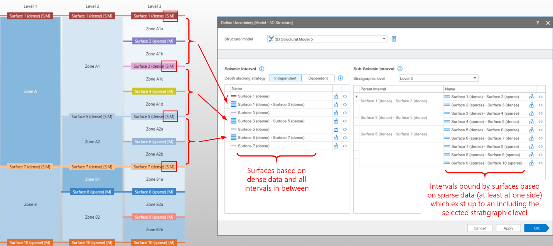
Example of how a structural model zonation, as visible in the 3D Structure Zonation View on the left, translates into two categories of intervals on the Define Uncertainty form. The 'seismic intervals' in the left table are intervals between structural model surfaces which were based on 'dense' data (recognized by the [S] printed behind their name in the 3D Structure Zonation View). The 'sub-seismic intervals' on the right are intervals between structural model surfaces which were based on 'sparse' data (recognized by the [M] printed behind their name in the 3D Structure Zonation View). click to enlarge
Stacking strategy (surfaces only)
On the form you can choose between 'Dependent' and 'Independent' stacking strategy. This option is only applicable to surfaces, not to intervals. 'Dependent' means that all uncertain surfaces derive their depth shift from a single SGS map (method SGS) or from a single multiplier value (Multiplier method). Note that for SGS, also one single variogram is used for all surfaces when choosing dependent stacking strategy. As a result, all surfaces will shift in a synchronous way (per whole stack-set in case of SGS and per whole surface in case of Multiplier method) upward or downward. The amount with which each surface shifts is defined by the standard deviation which is specified per surface. A typical example to apply 'Dependent' stacking strategy is when uncertainty comes from the seismic velocity model.
When 'Independent' stacking strategy is selected, each surface is sampled individually, i.e. a unique SGS map in case of method SGS and a unique multiplier value per surface in case of Multiplier method. Note that for SGS, each surface also has its own variogram. With 'Independent' stacking strategy, the uncertain surfaces can shift vertically in opposite directions (within each stack-set in case of SGS and per whole surface in case of Multiplier method). This strategy is only recommended when dealing with uncertain surfaces that are bounding thick zones.
To define uncertainty
- From the Structural Model drop-down list at the top of the form, select the Structural Model of interest. Upon selection:
- All the surfaces in your Structural Model which are based on dense data are listed in table 'Seismic Surfaces and Intervals' (left table) together with all the intervals in between those surface (see Seismic Intervals).
- The stratigraphic level that was used to construct the Structural Model is auto-selected in the 'Stratigraphic level' drop-down list located above table 'Sub-Seismic Intervals'.
- All intervals bound at least at one side by a surface based on sparse data, and which occur up to and including the stratigraphic level (see previous bullet point) appear in the table 'Sub-Seismic Intervals' (right table). See Sub-Seismic Intervals. Note that when an interval has children (i.e. the interval is subdivided at a deeper level), the child intervals are listed in the table, not the parent interval.
- Depth stacking strategy (surfaces only) Choose a dependent or independent stacking strategy for your surfaces by clicking on the respective button. By default, 'Independent' is selected. For more on stacking strategy, see Stacking strategy (surfaces only) above.
- Stratigraphic level The stratigraphic level you select from the 'Stratigraphic level' drop-down box is the 'deepest' level (i.e. the level with the highest number) at which sub-seismic intervals will be included in the 'Sub-Seismic Intervals' table. Any sub-seismic intervals existing at deeper levels in your 3D Structure Zonation View (see image above) will be excluded from the table. The stratigraphic levels available for selection are the shallowest stratigraphic level at which all 'seismic' surfaces occur, plus all deeper levels (if they exist). You can review your stratigraphic levels in the 3D Structure Zonation view, accessible via the Edit Model form in the Structural Modeling workflow. The default selection is the stratigraphic level that was used to build the Structural Model.
- To make surfaces and/or intervals uncertain Make one or more surfaces and/or intervals uncertain by clicking the uncertainty symbol at the end of the table row (
 ). You can apply uncertainty to either one of the two tables (or both), but be careful not to 'over specify', see tip note below. When made uncertain, the uncertainty symbol of the respective surface/interval is pink (
 ).
). - To fix one or more surfaces or intervals (optional) Fix (lock in place) one or more surfaces or intervals by clicking the lock at the end of the table row (
 ). When a surface is fixed, the lock shows a closed status (
 ). Be careful not to 'over specify', see tip note below.
 - When you have finished specifying uncertainty, click Apply (to save the settings and keep the form open) or click OK to save the settings and proceed with entering uncertainty settings (the application will jump successively to the appropriate form(s), dependent on your selections, i.e. the Depth form for uncertain surfaces, the Thickness (Seismic) form for uncertain seismic intervals and Thickness (Sub-Seismic) form for uncertain sub-seismic intervals).