How depth shifts are calculated
When depth and thickness uncertainty is applied, this means that surfaces (or, in case of method SGS, individual stack sets) move up or down according to the outcome of the depth shift map. The following sections describe how depth shifts of uncertain surfaces and intervals are calculated, and how those shifts can impact other surfaces and intervals in the same sequence. It is of major importance to understand these principles before you apply uncertainty to surfaces and/or intervals of your structural model.
In all of the following sections, when the terms 'uncertain', 'fixed' and 'unspecified' are used, this means:
- Uncertain surfaces and intervals: These surfaces and intervals are set to 'uncertain' on the Define Uncertainty form (see image below) and will move up/down (intervals will grow/shrink) according to the settings as specified on the Depth, Thickness (Seismic) and Thickness (Sub-Seismic) forms.
- Fixed surfaces and intervals: These surfaces and intervals are set to 'fixed' on the Define Uncertainty form (see image below) and stay unchanged. For surfaces this means they do not move up/down and for intervals this means they do not grow/shrink (i.e. they retain their original thickness). By setting surfaces/interval as 'fixed', you avoid shifting due to other (uncertain) surfaces/intervals in the same sequence.
- Unspecified surfaces and intervals: These surfaces and intervals do not have any applied setting on the Define Uncertainty form (see image below). These surfaces and intervals can potentially be impacted by uncertain intervals in the same sequence. For surfaces this means that they can move up/down and for unspecified intervals this means they can grow/shrink, due to the accommodation space needed by growing/shrinking uncertain intervals in the same sequence, see 'The principle of available space' below.
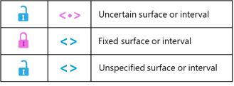
Blue symbols means 'no settings applied', i.e. the surface/interval is not fixed and not uncertain (default settings). Pink symbols mean 'you applied settings'. The pink lock means you 'fixed' the surface/interval; the pink uncertainty symbol means you made the surface/interval 'uncertain'. The lock and uncertainty symbol are mutually exclusive. click to enlarge
When you apply thickness uncertainty, this means that uncertain surfaces move up/down and uncertain intervals grow/ shrink according to the generated depth shift map. The necessary space to accommodate these shifts is provided by two potential ‘sources’ of space:
- 'Undefined' space above and below the model sequence. This means that when uncertain surfaces and intervals move, the surfaces and intervals above and below are freely moving along (up and/or down) and intervals retain their original thickness.
- Space taken from unspecified intervals. In this case, unspecified intervals act as 'space buffers', growing or shrinking as a reaction to meet the space needed by the uncertain intervals. In this case, unspecified intervals do not keep their original thickness.
To prevent unspecified surfaces from moving and unspecified intervals from growing/shrinking, the 'fix' option is provided on the Define Uncertainty form. Each surface/interval which is 'fixed' will retain its depth (in case of surfaces) or thickness (in case of intervals). There is a physical limit to the combination of applied 'uncertainty' and 'fixed' settings within a sequence, because uncertain surfaces/intervals ultimately need 'space' to move (see point I and II above). When the application cannot handle a particular combination of settings this is called 'over-specification'. 'Over-specification' on the Define Uncertainty form can lead to unintended results (i.e. the 'clipping' of intervals, which is explained in section 'How depth shift is calculated' further below). Note that 'over-specification' does not always trigger a warning in the application.
As explained in the previous section, unspecified surfaces and intervals can be impacted by shifts of uncertain intervals located above and/or below in the same sub-sequence. A sub-sequence is a series of surfaces/intervals that starts or ends with a ‘confining element’. A confining element is 'fixed' in place (except for its own uncertainty). Confining elements are:
- A fixed surface or fixed interval ('fix' option activated on the Define Uncertainty form, see image at the top).
- An uncertain surface ('uncertainty' option activated on the Define Uncertainty form, see image at the top).
- The outer surface of an uncertain or fixed interval that is located at the absolute top or base of the full modeling sequence. (There is one exception: when all intervals in the same (sub-)sequence are uncertain and/or fixed, then the outer surface is not a confining element.)
These confining elements act as 'fixed' boundaries to the sub-sequence. As a result, uncertain intervals within such confined sub-sequence take the space to grow/shrink from unspecified intervals within the same sub-sequence. This is schematically visualized in the image below.
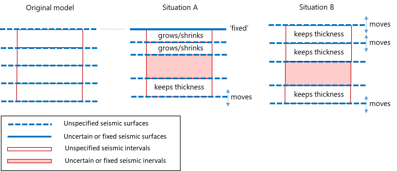
Figure 1: Illustration showing how confining elements impact unspecified intervals within in the same sub-sequence. Situation A: The two unspecified intervals are located between two uncertain elements and need to grow/shrink to accommodate the space needed by the uncertain interval. Situation B: The two unspecified intervals can freely move up and down as a whole (they can retain their thickness) to accommodate the space needed by the uncertain interval. click to enlarge
When a sequence has a confining element at both ends, it is called a 'confined (sub-)sequence', and its isochore is always retained. Figure 2 gives a hypothetical example of a sequence that is divided into three sub-sequences; two of them confined, one unconfined.
Whether unspecified intervals grow/shrink to accommodate for space needed by uncertain intervals, or whether they keep their thickness depends on their position in the sub-sequence and whether that sub-sequence is confined or not. The rules are as follows:
- When unspecified and uncertain intervals exist together in a confined (sub-)sequence, the unspecified intervals always grow/shrink proportionally [*].
- When unspecified and uncertain intervals exist together in a non-confined sub-sequence, then:
2.1. Unspecified intervals grow/shrink proportionally when they are positioned between two uncertain surfaces and/or intervals.
2.2. Unspecified intervals keep their thickness when they are not positioned between two uncertain surfaces and/or intervals (but move up/down as a whole).
[*] A set of sub-seismic intervals (for ‘seismic’ vs. ‘sub-seismic’ intervals, see Hierarchy of seismic and sub-seismic surfaces and intervals) is always a confined (sub-)sequence between the 'seismic' surfaces of the parent interval. Therefore sub-seismic intervals always grow/shink proportionally. Only when sub-seismic intervals have no 'parent interval' (i.e. 'orphan intervals') they do not form a confined sub-sequence and the full set of rules applies.
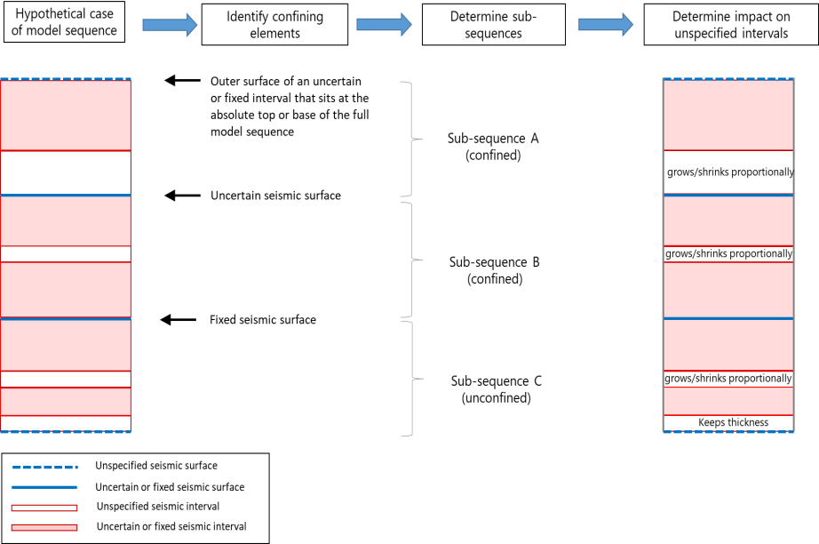
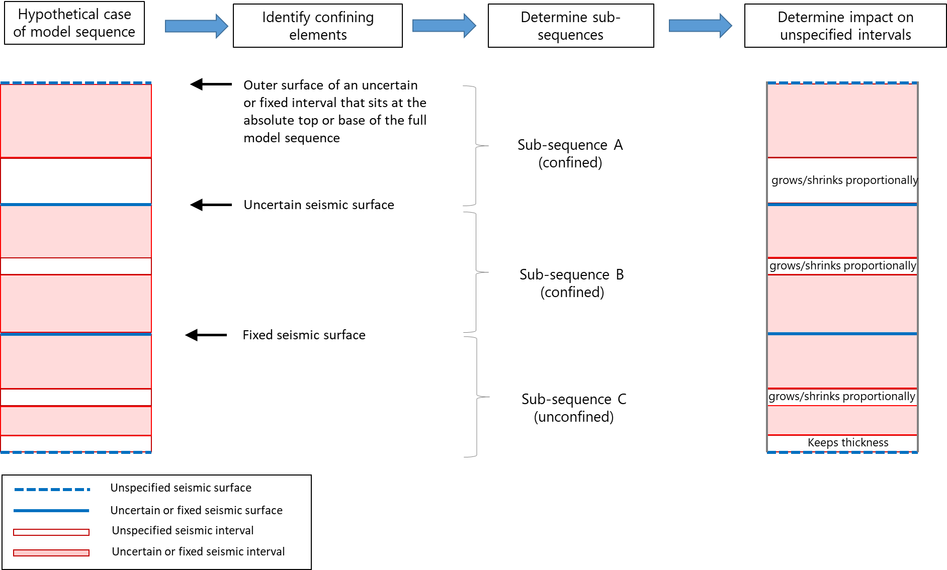
Figure 2: Example of a model sequence that is divided into three sub-sequences based on ‘confining elements'. Each sub-sequence is treated independently in terms of depth shift calculations. The presence and location of confining elements determines whether unspecified intervals grow/shrink. click to enlarge
The concept of depth and thickness uncertainty in the application is hierarchical which means that there is a distinction between first order (called 'seismic') and second order (called 'sub-seismic') surfaces and intervals. On the Define Uncertainty form, this distinction is automatically applied to your structural model and you will find the 'seismic' and 'sub-seismic' tables on that form automatically filled (upon selection of your structural model) according to this concept.
After you have applied uncertainty settings to the surfaces and intervals in the tables (i.e. 'uncertain', 'fixed', 'unspecified') these settings will be handled by the application in a hierarchical way. Per realization, first the depth shifts based on the 'seismic' table are calculated. The result consists of shifted seismic surfaces (thickness uncertainty is converted into depth) which can be considered as a 'framework'. Secondly the thickness shifts for the intervals in the sub-seismic table are calculated. These shifts are 'fit' proportionally within the 'framework' as set by the 'seismic' surfaces and as such, converted into depth. This way, uncertainty applied to (lower-order) sub-seismic intervals never impacts the position of (higher-order) seismic surfaces. See the next paragraphs which explain in more detail the calculations per 'seismic' and 'sub-seismic' category.
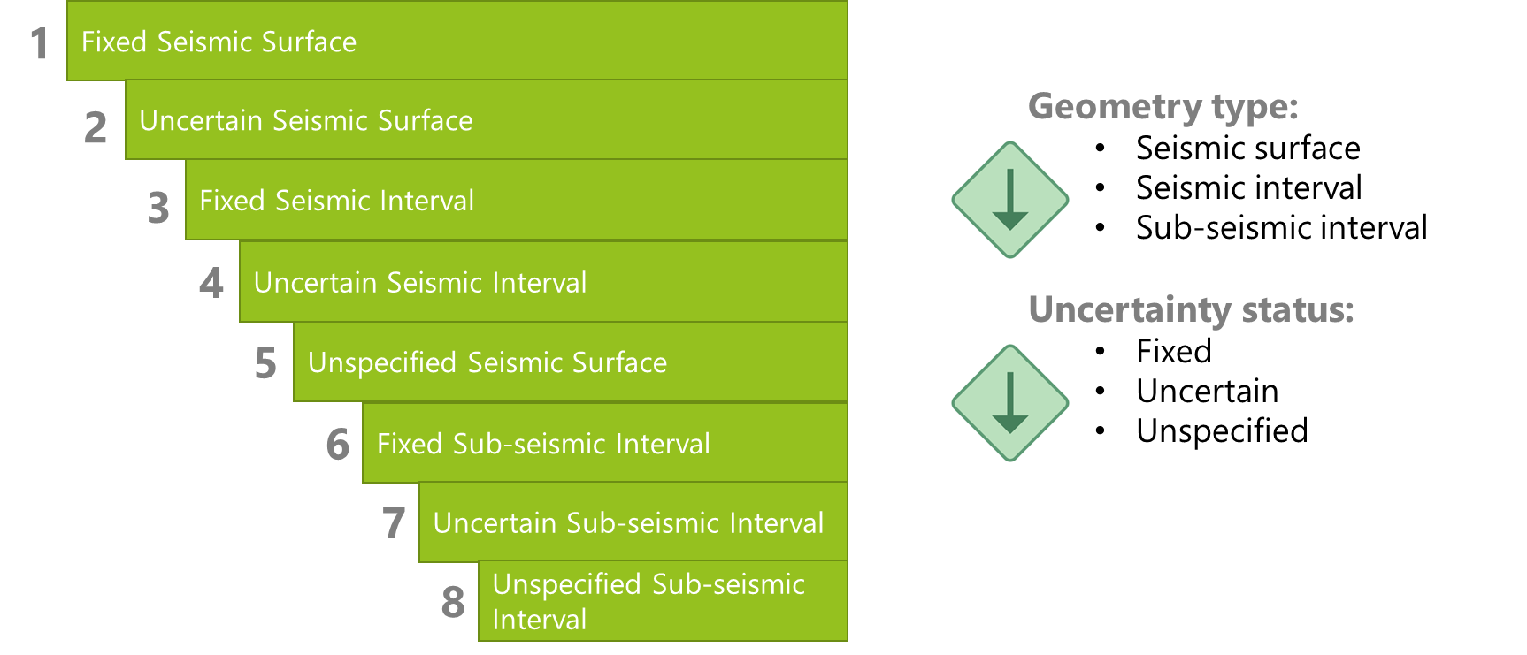
Figure 3: Uncertainty applied to 'seismic' and 'sub-seismic' surfaces and intervals is handled hierarchically by the application, ensuring that shifts resulting from 'sub-seismic' intervals never impacts the seismic surfaces. click to enlarge
Depth shift calculations of 'seismic' surfaces and intervals
Depth shifts for 'uncertain', 'fixed' and 'unspecified' surfaces and intervals (as specified on the Define Uncertainty form) are calculated in the following order of priority: fixed seismic surfaces > uncertain seismic surfaces > fixed seismic intervals > uncertain seismic intervals > unspecified seismic surfaces.
In more detail the order is as follows:
- 'Fixed' seismic surfaces are 'locked' in place (no depth shift).
- Depth shifts for 'uncertain' seismic surfaces are calculated (based on the settings of 'Depth' form).
- 'Fixed' seismic intervals are 'locked' (no growth/shrinking allowed). To do this, the application associates its top/base surfaces to either 'no depth shift' or to 'similar depth shift' as follows:
- In case no 'uncertainty' is applied at seismic scale, then top/base surfaces of 'fixed' interval stay in place with no depth shift.
- In case 'uncertainty' is applied at seismic scale, then top/base surfaces of 'fixed' interval acquire the same depth shift to retain their thickness. The amount of this shift depends on the depth shifts of uncertain seismic surfaces and intervals.
- 'Uncertain' seismic intervals undergo thickness changes based on the settings of the 'Thickness (Seismic)' form. Conversion of their top/base surfaces into depth is determined by their position within the (sub-)sequence, the presence of unspecified seismic intervals in that (sub-)sequence and whether that (sub-)sequence is confined or not (see section 'Impact of uncertainty on unspecified intervals' and figure 2).
- When in a confined (sub-)sequence, the shift of the top/base surfaces is proportional and depends a) on the total thickness of all unspecified seismic intervals within the same (sub-)sequence and b) on the vertical distance of the middle of the uncertain interval to the top/base of the confined (sub-)sequence. This to prevent unnecessary stretches/squeezes in the structural model.
- Depth shifts of unspecified seismic surfaces are calculated per linear interpolation or are equivalent to the depth shifts of their neighboring uncertain seismic surfaces.
- When in a confined (sub-)sequence, their depth shift maps are calculated per linear interpolation (between depth shift maps of two uncertain seismic surfaces); when in an unconfined (sub-)sequence, they shift upward/downward with the same rate as the shallowest and deepest uncertain/fixed seismic surfaces or interval boundaries (see the unspecified interval at the top of the sequence in figure 4).
- In case of interference of shifted seismic surfaces (i.e. not enough space is available to perform the shift) then clipping happens of one surface onto the other according to the same prioritization as under steps 1-5 and figure 3 above (e.g. uncertain surfaces gets clipped onto fixed seismic surfaces). In case the surfaces have equal 'priority', they get proportionally clipped onto each other.
- All surfaces and intervals in the seismic category have reached their final position for the realization. The application proceeds with the shift calculations of 'sub-seismic' intervals (step 8-11 below), hereby always keeping the final position of the 'seismic' surfaces unchanged.
- 'Fixed' sub-seismic intervals are 'locked' (no growth/shrinkage allowed).
- Initial growth/shrinkage is calculated for 'Uncertain' sub-seismic intervals based on the settings of the 'Thickness (Sub-Seismic)' form.
- The sum of growth/shrinkage (step 9) of all uncertain sub-seismic intervals is calculated per each 'parent' seismic interval and proportionally 'fit' into the new thickness of the parent seismic interval.
- If the sum of the initial new thickness of sub-seismic intervals is greater than the new thickness of the parent seismic interval, then the sub-seismic intervals are squeezed (shrunk). Squeezing takes place in the following order: first unspecified sub-seismic intervals; if this is not enough, then uncertain sub-seismic intervals; if not enough, then fixed sub-seismic intervals get squeezed (see figure 5).
- If the sum of the initial new thickness of sub-seismic intervals is smaller than the new thickness of the parent seismic interval, then the sub-seismic intervals are stretched (get thicker). Stretching takes place in the following order: first unspecified sub-seismic intervals get stretched; if not available, then uncertain sub-seismic intervals get stretched; if not available, then fixed sub-seismic intervals get stretched.
Thickness compensation rate (squeezing/stretching) at each priority level is applied proportionally. The weight factor is derived from the ratio of the initial new thickness of sub-seismic intervals / sum of the initial new thickness of sub-seismic intervals. This means that an initially thin interval would receive less stretch or squeeze, so that the principle of subsurface layering/architecture remains the same. - After deriving the new thicknesses for all sub-seismic intervals, sequentially from top or bottom of each parent interval, depth shift maps of the sub-seismic surfaces are created.
Depth shift calculations of 'sub-seismic' surfaces and intervals
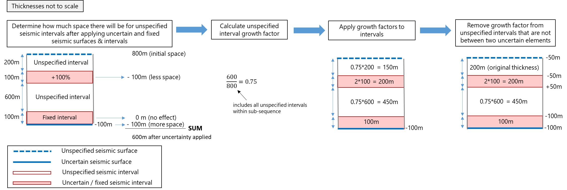
Figure 4: Example of shift calculations of seismic surfaces/intervals. The growth-factor is applied proportionally to all unspecified intervals in the (sub-)sequence, after which unconfined intervals will be set back to their original thickness. In case of method SGS, this calculation is done independently per stack set. click to enlarge
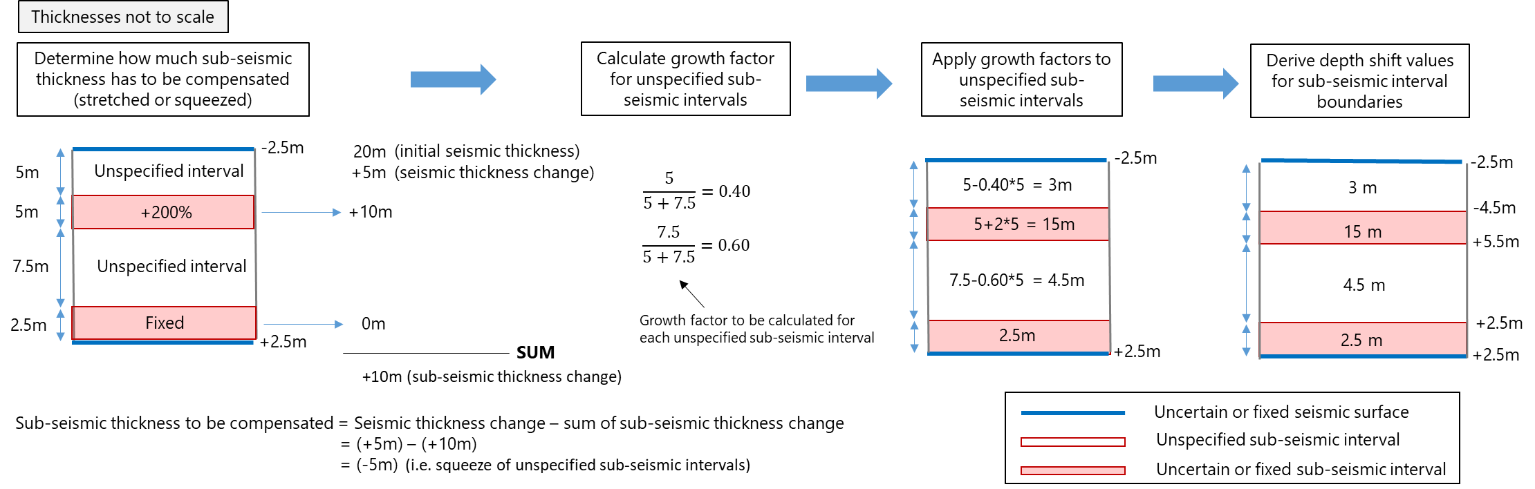
Figure 5: Example of shift calculations of sub-seismic intervals. Sub-seismic growth/shrinkage is 'fit' between seismic surfaces after thickness change. In the above example, the total growth of sub-seismic intervals is 5 meter, to be accommodated by proportional shrinkage of the unspecified intervals. click to enlarge
As a general rule do not assign thickness uncertainty to a confined (sub-)sequence. Confined (sub-)sequences typically result from applying depth uncertainty to multiple surfaces. As such, applying thickness uncertainty in combination with multiple depth uncertain surfaces needs to be done with care:
- Multiple uncertain surfaces in combination with thickness uncertainty can easily lead to over-specification (figure 6, bottom three images). In case you want to apply depth uncertainty to multiple surfaces, do not combine it with thickness uncertainty and for your own comprehension, make all surfaces uncertain (figure 6, upper left image).
- In case you want to apply thickness uncertainty in combination with multiple depth uncertain surfaces, make sure the distance between both uncertain surfaces is big enough for the surfaces to flex independently and do not leave a single interval unspecified (figure 6, upper right image).
It is recommended to avoid growth/shrinkage of unspecified intervals, except when you have a thick, unimportant zone that you consciously use to accommodate the space needed by uncertain intervals. You can avoid growth/shrinkage of unspecified intervals by not leaving a single interval unspecified between uncertain elements but make all intervals uncertain (figure 6, four images with uncertain intervals in top row).
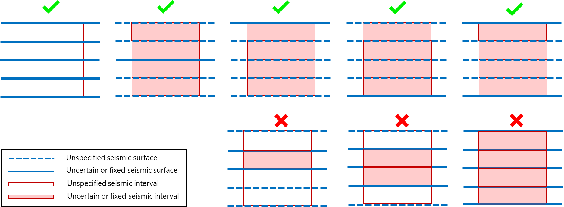
Figure 6: To avoid growth/shrinkage of unspecified intervals, it is recommended to not leave them unspecified. Scenarios at the base are invalid (the fixed/uncertain intervals are in conflict with the fixed/uncertain surfaces and cannot be handled by the application). click to enlarge
Depth and thickness uncertainty in JewelSuite is an implicit approach (see Concept of depth and thickness uncertainty in the application) which makes use of simplifications with respect to the structure and geometry and which 'mimics' structural changes via properties (e.g. depth properties), as opposed to an explicit approach where the geometry of the model would be completely recalculated and modified. The major advantage of an implicit approach over an explicit approach is speed as the application can quickly generate many different uncertain realizations. But as the full geometry is not recalculated and generated, there are some implications:
(1) ‘Impossible’ geometry
As the full geometry is not modeled, there is a risk of 'impossible geometries'. Two rules are applied to prevent severe issues from occurring. These rules are:
- When cells in the grid received negative volumes after running the Volumetrics Study, the shifts are modified in such a way that the cells receive 0 volume instead.
- Cells that had no thickness cannot get thickness when applying depth and thickness uncertainty.
These two rules are generally applied, but are of particular importance around pinch-outs.
(2) Discontinuities
Around discontinuities (faults, as well as unconformities and intrusions from the fault model), some simplifications are applied. When discontinuities truncate uncertain surfaces, not all depth and thickness information is available at all locations where it is required for uncertainty calculations. If modeled explicitly, this information would be fully re-modeled including complex inter- and extrapolation algorithms that are applied during the Structural Modeling and Gridding workflows. However, these time-consuming and complex calculations are not done in the implicit Depth and Thickness Uncertainty workflow, and approximations are used instead. The main approximation is that when data for a specific surface is missing in a place where it is required, the average depth of that surface is used. Depending on the actual geometry and structural uncertainty settings, this can lead to more irregularity around discontinuities.