Concept of depth and thickness uncertainty in the application
When running a Volumetrics Study with depth and thickness uncertainty, per realization equally probable depth shift realizations of your 3D structural model are created. A depth shift realization consists of a set of depth shift maps (one map per shifted horizon surface) which are based on Sequential Gaussian Simulation (SGS) or Multiplier method (see methods). As the structure of the structural model is not physically updated, the depth and thickness uncertainty is called 'implicit'. For SGS these shift maps show the typical SGS-induced spacial variability, while for Multiplier method these shift maps show a bulk shift per impacted surface. Per chosen method, various parameter settings need to be specified which, in combination with the sample (drawn in the study) result in the ultimate depth shifts per realization.
In each realization upon creation of the depth shift map, the depth shift map is re-interpolated using the area settings of the selected 3D grid and applied to the target 3D grid properties.
Subsequently, modified cell center depth values are used for fluid model level detection and saturation calculations. Each realization has its own depth shift maps and updated 3D grid properties. To actually obtain the properties in the JewelExplorer of one such realization (e.g. the P90 realization), you have to Re-run and save single realization (option on the Results Summary form of study > Volumetrics Study strip). This 'saved realization' (a new solution file) will, regarding depth and thickness uncertainty, contain the following:
- An auto-generated Surface Set containing tri-mesh surfaces representing the depth shift realization.
- The applied depth shift map called '<name of the structural model>DepthShiftMap' in folder Data > Maps.
- Updated fluid model properties in folder 3D Grid > Fluid Model (e.g. Cell Volume Oil Leg, Height Above Free Water Level).
- Updated saturation model properties in folder 3D Grid > Saturation Model.
- Implicit depth shift properties in folder 3D Grid > Depth and Thickness Uncertainty:
- Base shift (used for calculation)
- Top shift (used for calculation)
- Cell center depth - modified (for QC purposes)
- Cell volume - modified (for QC purposes)
- Cell volume difference (for QC purposes)
- Vertical cell thickness - modified (for QC purposes)
- Vertical cell thickness difference - relative (for QC purposes)
Because the depth and thickness uncertainty approach is implicit, in the 'saved realization', the 3D structural model and 3D grid (and its geometrical properties including 'Cell center depth') stay the same as in the reference model. They have not shifted.
To reproduce the 3D grid or 3D grid geometrical properties, you can use the Property Calculator in combination with the depth shift maps. You can also use the implicit depth shift of the 'saved realization' as input to dynamic simulation, see Using implicit depth realizations for dynamic simulation.
Preview options
When setting up depth and thickness uncertainty with the Depth and Thickness Uncertainty workflow, it is possible to preview shift maps with the workflow input forms (i.e. 'Depth', 'Thickness (Seismic)' and 'Thickness (Sub-Seismic)'. Apart from the fact that these maps only represent one realization, they only take into account the uncertainty settings for that particular uncertainty (i.e. depth or thickness) and do not incorporate the combined effect of the (hierarchically handled) depth and thickness uncertainty at seismic and sub-seismic level. These maps are therefore only meant to QC the input settings for that particular uncertainty (depth or thickness). Preview shift maps generated with the QC Uncertainty button (in the Tools section behind the Depth and Thickness Uncertainty workflow), however, do show a realization for the combined effect of all uncertainty inputs (depth and thickness). But note that also these maps are for QC purposes (of your input settings) only, and that they represent the result of only one (random) realization.
Well correction
As depth shifting can result in mis-ties between well data and surface data (i.e. their final positions in the structural model), a well correction step is provided in the Depth and Thickness Uncertainty workflow. The settings you specify there, will be used to nullify depth shift values around wellbore intersections, to ensure that well-ties are preserved around wellbores.
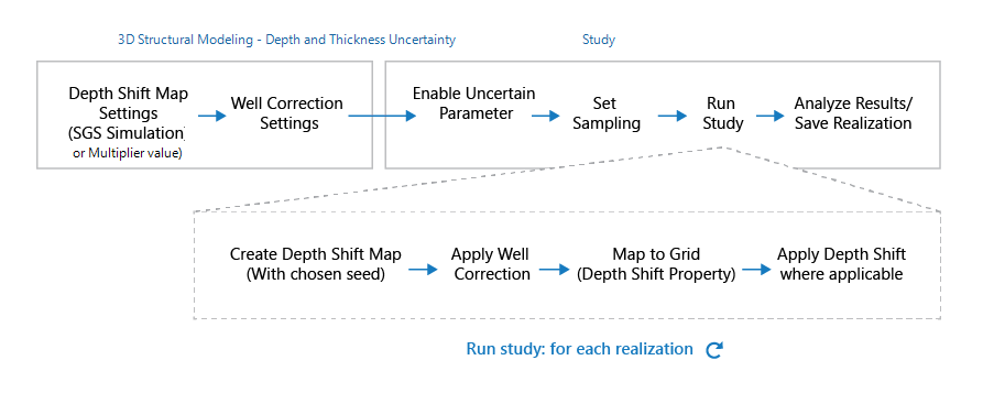
Flow-diagram for the depth and thickness uncertainty implementation in the application. click to enlarge
For how depth shifts are calculated, see How depth shifts are calculated.