Well Table
The Well Table allows you to view and edit well specific information including well names, locations, states, and perforations. This view has different tabs that each allow you to quickly reference basic well data and easily change it as needed. When changes are made in this view to data like well locations, names, and coloring, those changes are carried throughout all menus and views in the user interface.
This view features additional options for sorting data in their tables. These are available by right-clicking the column header area and selecting from the context menu.

Well heads tab. click to enlarge
The Well Heads tab displays (and allows you to edit some of) the following information for each well:
- Name - Well name.
- UWI - Unique well identifier corresponding with the well.
- Display Name - Name of the well when shown in the user interface.
- Short Name - Short name representation of the well.
- Site - The well location in terms of onshore or offshore.
- Mudline/Water Depth - (Offshore well) The mudline depth or water depth, referenced to Mean Sea Level. A positive value means below Mean Sea Level.
- Water Density - (Offshore well) The sea water density.
- Ground Level - (Onshore well) The ground level, referenced to Mean Sea Level. A positive value means above Mean Sea Level.
- Water Table - (Onshore well) The water table, referenced to Mean Sea Level. A positive value means below Mean Sea Level.
- Easting, Northing - The location (easting and northing) of the well in the projected coordinate system.
- Longitude, Latitude - The coordinates (latitude and longitude) of the well location in the geographic coordinate system.
- Color - The color of the well used throughout the user interface.

Wellbores tab (not all columns are visualized). click to enlarge
Similar to the Well Heads tab, the Wellbores tab displays (and allows you to edit some of) the following information for each wellbore:
- Name - Wellbore name.
- UWBI - Unique Wellbore Identifier.
- Display Name - Name of the wellbore when shown in the user interface.
- Short name - Short name representation of the wellbore.
- Wellhead - The wellhead that the wellbore is connected to.
- Parent Wellbore - In the case of a sidetrack, this displays the wellbore the sidetrack is a child of.
- Tie-in/KOP MD - For the main wellbore: the measured depth (MD) of the initial wellbore node point, relative to the well head location. For a sidetrack: the kick-off point from the parent hole. The KOP/MD is measured from the sidetrack DFE.
- Tie-in TVDSS - The true vertical depth subsea (TVDSS) at the tie-in/KOP MD.
- Tie-in Inclination, Tie-in Azimuth - The wellbore inclination/azimuth at the tie-in MD.
- Tie-in Delta Easting, Tie-in Delta Northing - The distance in easting/northing direction between the initial wellbore node point and the well head of the main borehole.
- Air gap - The distance between the DFE and Ground Level (Onshore well) or between DFE and Mean Sea Level (Offshore well). A positive value means above Mean Sea Level.
- DFE - The Derrick Floor Elevation, referenced to Mean Sea Level. A positive value means above Mean Sea Level.
- Status - Status of the wellbore: Existing, Planned or Unknown.
- Current State - Current state of the wellbore: Producer, Injector, Idle or Unknown.
- Spud Date - Spud date of the wellbore.
- Operational Status - Operational status of the wellbore; On, Off or Unknown.
- Easting, Northing - The easting/northing location of the wellhead (main borehole) or tie-in/KOP MD (for sidetrack).
- Bottom Easting, Bottom Northing - The easting/northing location at TD (total depth) of the wellbore.
- Bottom TVDSS - The true vertical depth subsea (TVDSS) at TD (total depth) of the wellbore.
- Bottom MD - The measured depth (MD) at TD (total depth) of the wellbore.
- In Model Data - When the checkbox is checked (default), some or all markers (to be specified in the 'Use for modeling' column of the Marker Table) of the wellbore are incorporated in the various modeling processes in the application where markers are used as input. When the checkbox is unchecked, all markers of the wellbore are ignored during modeling steps. The state of the 'In Model Data' checkbox in the Well Table can also be controlled via the 'In model data' option in the context menu of the wellbore.
- Color - The color of the wellbore used throughout the user interface.

Logs tab click to enlarge
The Logs tab provides an overview of minimum and maximum values for selected wells and continuous logs. Similar to the way in which data is visualized in the 3D View or Well View, you use the JewelExplorer to select the wells and continuous logs that you want to evaluate; to view the data for a selected well-log combination, check the box in the JewelExplorer for both the well and log of interest. While data for discrete logs is not displayed, a checkmark in the column for a discrete log indicates that the log is present in the well.
The tab view consists of the following features, though it is important to note that all data is read-only:
- Selected logs - The top row of the view consists of the logs that you have chosen to display in the JewelExplorer.
- Absolute min - max - This row displays the absolute minimum and maximum values for the log, across all selected wells.
- Wells - In the first column, under the absolute min - max row, each of the wells that you have selected in the JewelExplorer is listed.
- Data - The cell at the intersection of each well-log combination displays the minimum and maximum values for the particular log in the particular well.

States tab click to enlarge
The States tab displays and allows you to edit the following information for each wellbore:
- Wellbore name - Wellbore name, this corresponds to the names set in the Wellbores tab.
- Start Date - The starting date for the wellbore.
- End Date - The end date for the wellbore.
- Type - Allows you to select the wellbore type; options include Unknown, Producer, Injector, and Idle.
- Status - Allows you to set the status of the wellbore; options include Unknown, Existing, and Planned.
- Phase - Allows you to select the wellbore phase; options include Unknown, Oil, Gas, Water, Liquid, and Solvent.
- Condition - Allows you to select the wellbore condition; options include Unknown, Reservoir, and Surface.
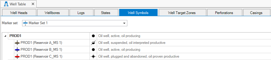
Well Symbols tab click to enlarge
You can use the Well Symbols tab to view
A well symbol is defined by setting four categories: Well type, technical status, fluid type and hydrocarbon status. With this stepwise approach, you can easily assign a well symbol with a complete well description.
To set your well symbols at wellbore level
First click the blue pencil icon (![]() ) to open the Edit Well Symbol form.
) to open the Edit Well Symbol form.
- From the Well drop-down list, select the wellbore you want to set a symbol for.
- Leave the Marker selection set to None.
- For each category (i.e. well type, technical status, fluid type and hydrocarbon status), make a selection from the drop-down list. You have to work step by step from top to bottom and your selection sets a filter for the next selection.
- Click Apply to assign the well symbol and keep the form open or click OK to assign the well symbol and close the form.
To set your well symbols at marker level
First make sure the marker set of interest is selected on the Well Symbols tab and click the blue pencil icon (![]() ) to open the Edit Well Symbol form.
) to open the Edit Well Symbol form.
- From the Well drop-down list, select the wellbore of interest.
- From the Marker drop-down list, select the marker you want to set a symbol for.
- For each category (i.e. well type, technical status, fluid type and hydrocarbon status), make a selection from the drop-down list. You have to work step by step from top to bottom and your selection sets a filter for the next selection.
- Click Apply to assign the well symbol to the marker and keep the form open or click OK to assign the well symbol to the marker and close the form.

Well target zones tab click to enlarge
The Well Target Zones table lists the target zone(s) that have been defined and the entry and end depth of the wells. Target zones are mainly used in the planning of horizontal wells in a well pad configuration, however, the table lists all wells whose well design settings include the selection of a target zone.
- Wellbore - Name of the wellbore
- Well target zone - Name of the well target zone
- Entry MD - MD depth at which the wellbore enters the well target zone
- End MD - MD depth at which the wellbore exits the well target zone
- Length in well target zone - Length of the wellbore in the well target zone
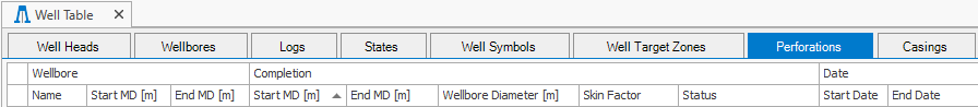
Perforations tab click to enlarge
The Perforations tab displays, and enables you to edit, the wellbore perforation information.
Options on the Perforation tab include:
- Wellbore Name - Wellbore name that the perforation is for.
- Top MD and Base MD - The top and base depths of the wellbore.
- From MD and To MD - The start and end MD (Measured Depth) of the perforation along the wellbore.
- Wellbore Diameter - Diameter of the wellbore. This value is used to calculate the well index for input to a simulator.
- Skin Factor - Define the skin factor which is used in the Productivity Index (PI) computation.
- Status - Allows you to set whether the perforation is open or closed.
- Start Date - The starting date for the perforation.
- End Date - The end date for the perforation.
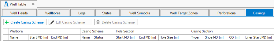
Casings tab click to enlarge
The Casings tab shows the casings in the well. You can click on the Create Casing Scheme button  , above the table, to open the casing scheme form and create a new casing scheme. To edit an existing one, select a wellbore entry in the table and click on the Edit Casing Scheme button
![]() to open the casing scheme form. To delete a casing scheme, first select the wellbore in the table for which you want to delete the casing scheme. Select the casing scheme you want to delete from the Name drop-down list, under Casing Scheme. Click on the Delete Casing Scheme button
to open the casing scheme form. To delete a casing scheme, first select the wellbore in the table for which you want to delete the casing scheme. Select the casing scheme you want to delete from the Name drop-down list, under Casing Scheme. Click on the Delete Casing Scheme button to open the delete dialog. If a wellbore has more than one casing schemes, after deletion the next available casing scheme will automatically appear in the table, under Name in the Casing Scheme section.
The table in the Casings tab provides an informative overview of a well's main casing components. Each section lists information related to the depth, dimensions and characteristics of the components, such as names and types:
Wellbore
- Name - The name of a wellbore with a casing scheme.
- Start MD - The starting MD (Measured Depth) of the wellbore.
- End MD - The end MD of the wellbore.
Casing Scheme
- Name - The name of a casing scheme.
- Status - Shows the status of the casing scheme; status include Design and Actual.
Hole Section
- Start MD - The starting MD (Measured Depth) of the wellbore hole.
- End MD - The end MD of the wellbore hole.
- Hole Size - Diameter of the wellbore hole.
Casing Section
- Type - Shows the selected casing type; types include Casing, Liner and Openhole.
- Shoe MD - Depth of the casing shoe.
- Outer Diameter - Outer Diameter of the casing.
- Liner Start MD - Top depth of liner.