Fault Holes Detector warnings: holes in faults in the 3D grid
In some cases, you may encounter gaps in the faults in your 3D grid (called 'fault holes') that cannot be explained directly by the input data. As a result, artifacts may occur in the constructed surfaces around these fault holes. These fault holes are a localized version of the holes described in Holes in constructed surfaces or 3D grids and are restricted to a particular fault. Therefore they do not show up as a complete rectangular hole throughout the 3D grid.
Some fault holes may not be worthwhile to resolve, for example when they occur at the edge of a model with no surfaces nearby, whereas others may cause severe issues, like in the example below.
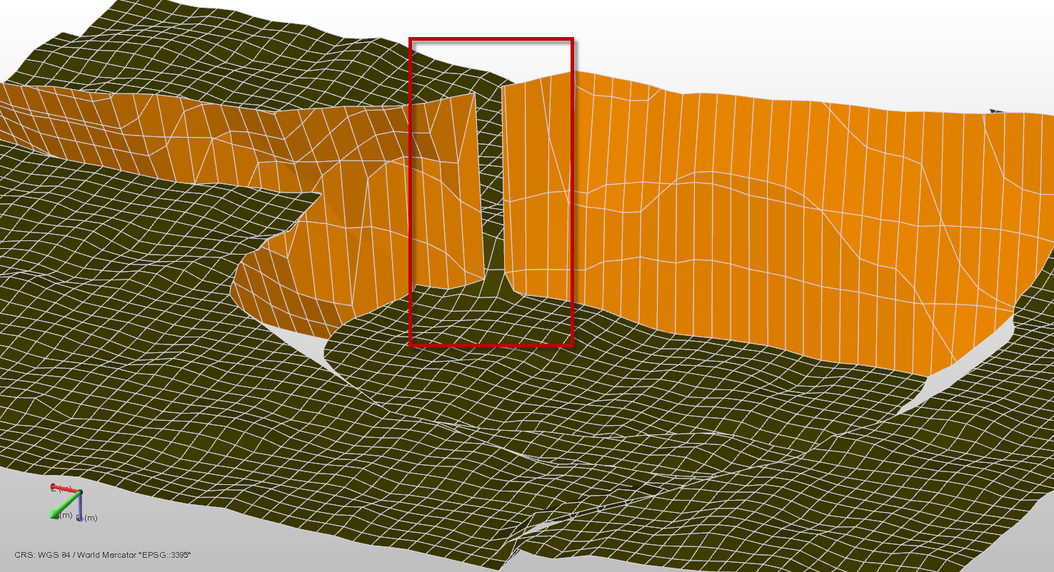
Gridding result showing a grid fault (orange) and a grid horizon (green). The fault hole is located in the red box. In the image below you can see that the input fault, on the basis of which the grid fault was created, is of good quality (i.e. it shows no gap). The fault hole has resulted in a flexure in the constructed horizon, i.e. the hanging wall and footwall sides of the fault are connected instead of offset by the fault. The possible cause of the fault hole might be the changing dip orientation of the fault; at the fault hole location the footwall swaps to hanging wall (and vice versa) click to enlarge
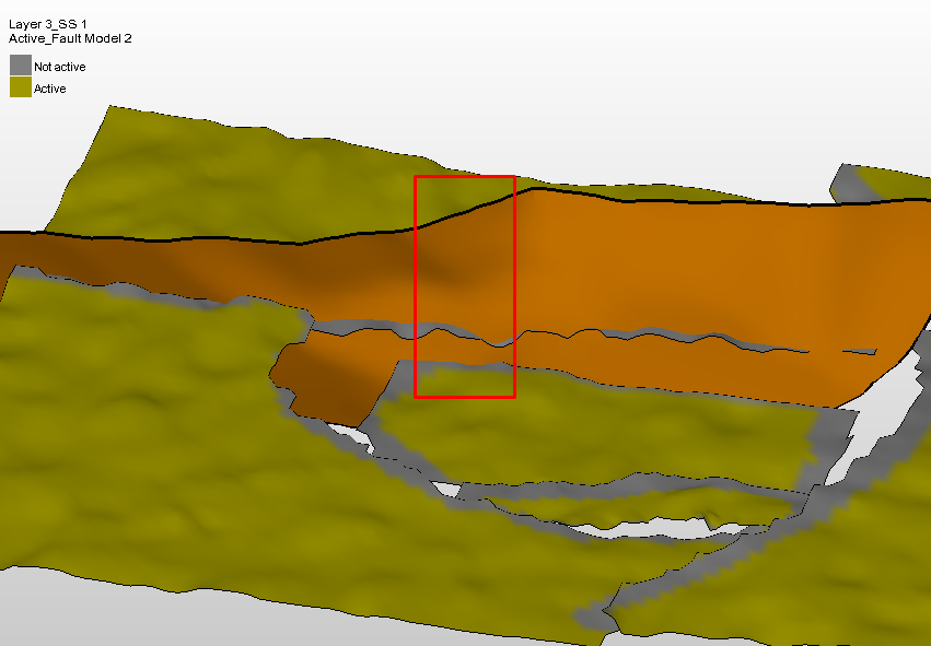
Input data to the 'Construct Surfaces' step, with a fault (orange) and a horizon (green) and with 'horizon clean-up' applied (gray regions are 'inactive' and will be discarded as input data). Note that the input fault is continuous at the location of the red square. After 'construct surfaces' however, a 'fault hole' will appear at that exact location in the grid fault, resulting in a flexure in the constructed surface (see image further above). The probable cause is the change in dip direction of the input fault around the location of the red square) click to enlarge
Where encountered
- model > 3D Structure > Construct Surfaces / Fault Cutoff Line Edits
- model > 3D Grid > Create Jewel Grid
Cause
Fault holes in the grid, similar to the holes described in Holes in constructed surfaces or 3D grids, result from the gridder not being able to resolve a geometrical situation introduced by a particular combination of input surfaces and data settings. Many fault holes can be attributed to strong curvatures in the input data, particularly where sub-vertical faults cause the footwall to swap into the hanging wall (and vice versa) over a short distance along the fault. The support for such geometries in the gridder is limited. Furthermore, (locally) poor quality input data or intersections can also lead to fault holes.
Locating the issue
Fault holes are detected automatically during creation of the QC grid (created during the 'Construct Surfaces' step) or the 3D grid. Upon creation of the QC grid or 3D grid, the Output Information pane gives the warning (if any) in the form of [Fault Hole Detector]} # Holes detected in fault <name of fault>, including a specification of the location of the fault hole in I,J positons (see image below).
Based on the content of the warning, you can then locate the issue in the grid fault by displaying the grid fault in your 3D View. You find the grid fault in the JewelExplorer under 3D Grids > 'name of 3D Grid' (or 'name of QC Grid') > Faults. To only display the grid faults, make sure you have the Grid checkbox unchecked (see image below).
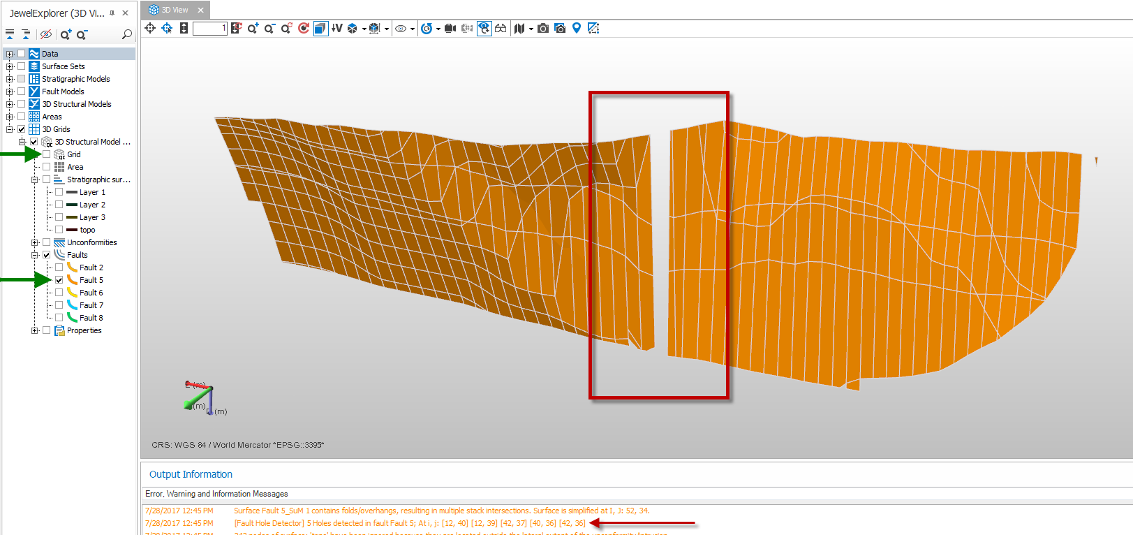
Displaying a grid fault in the 3D View by selecting it (checking the box) in the JewelExplorer under 3D Grids > 'name of QC grid' > Faults (or 3D Grids > 'name of 3D grid' > Faults) click to enlarge
Note that the faults shown in the 3D Structural model or Fault Model are the original tri-meshes, and will therefore look differently (without holes) as they are input data to the gridding process. To locate fault holes, you should always look at the grid faults, as they are used to construct the horizon surfaces. Any fixes should be done on the input tri-meshes.
How to fix the issue
To fix fault holes in cases with poor input data, the steps and tools described in Holes in constructed surfaces or 3D grids apply.
In cases where your input data does not show flaws or artifacts, smoothing of the input tri-mesh (either manually or with the tri-mesh tools) may resolve or alleviate the issue. But note that the gridder has only limited support for cases as mentioned above.