Flexures of 3D grid layers around fault model inconsistencies
In some cases, you may encounter unwanted flexures in constructed surfaces or 3D grids after performing the Structural Modeling and/or 3D Gridding workflows. See image below, where a k-layer is ‘smeared’ along the fault where is should have been properly offset. These flexures can have multiple causes, see section 'Cause' below.
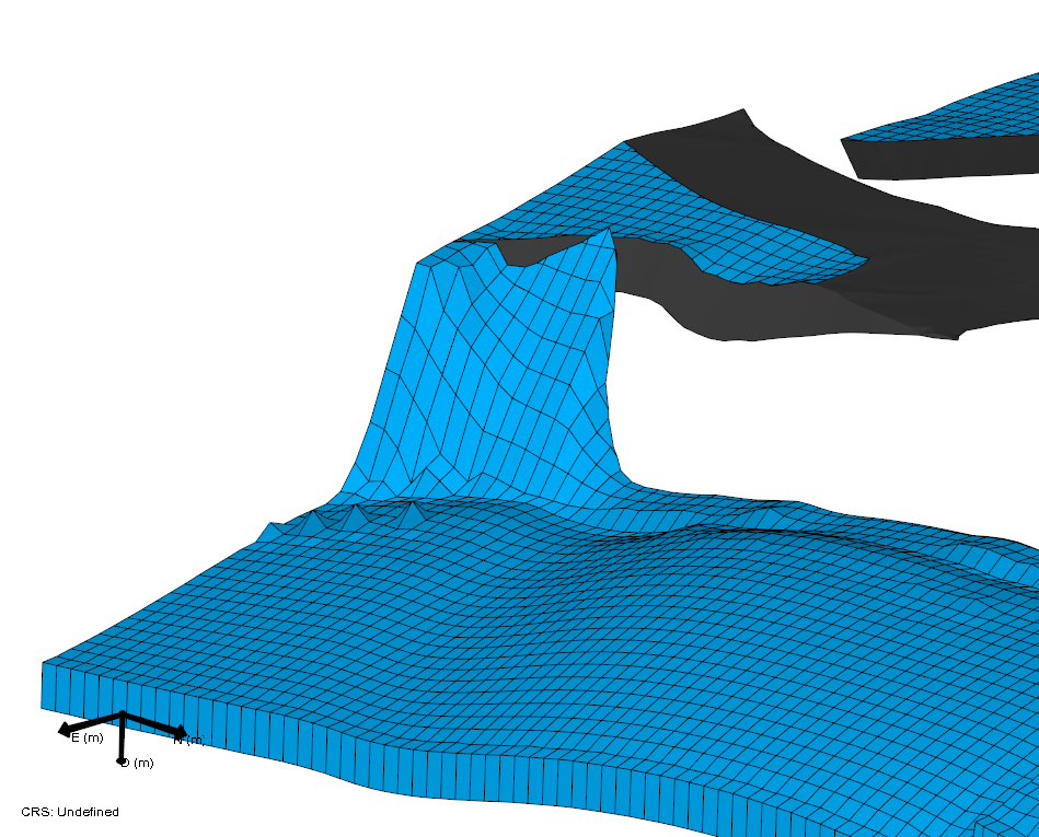
Artifact in the k-layering of a 3D grid. Here the k-layer should be properly offset by the fault, instead, the layer is turned into a flexure. This artifact may be related to inconsistencies in the fault model click to enlarge
Where encountered
- model > 3D Structure > Construct Surfaces / Fault Cutoff Line Edits
- model > 3D Grid > Create Jewel Grid
Cause
Local flexures are mostly attributed to two different causes:
- Not covered in this section: inconsistencies in the geometry of other surfaces (i.e. non-fault model surfaces) particularly due to poor horizon clean-up, see:
- Covered in this section: inconsistencies in the assigned fault model
In case the flexures are caused by inconsistencies in the fault model, this often means the fault model is not completely watertight along sections where it should be. The following images show examples of the consequences for gridding and how the artifact cascades from the structural model to the 3D grid with k-layers.
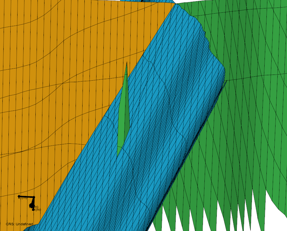
Detailed view of the faults contained in the QC grid of a structural model. By giving the faults individual colors (via Autocreate Colors on the Faults context menu), you can see the inconsistency more easily. Here the green fault is extended through a small gap, beyond the blue fault. This artifact may not yet cause problems in the 3D structural model, but when this artifact is carried along into the 3D grid, the internal k-layering is affected (see next image) click to enlarge
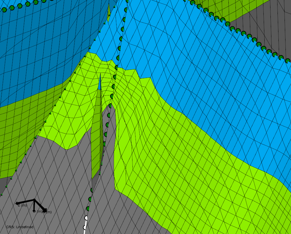
Same location as previous image, but after gridding has been performed (the faults that are displayed, are the faults contained in the 3D grid, rendered using color coding for ZoneID). It is clearly visible that the k-layers of the grid are distorted by the artifacts in the fault (see previous image) click to enlarge
How to fix the issue
The flexures discussed in this topic are a different manifestation of the same issues (i.e. fault model inconsistencies) which are described in Holes in constructed surfaces or 3D grids. Refer to the paragraph 'How to fix the issue' in that section for the steps to take to solve the issues.
Result
After using the various options to clean-up the faults as described in Holes in constructed surfaces or 3D grids (paragraph ‘How to fix the issue’), fault intersections should be watertight where required. As a result, there should be no flexures anymore in the produced grid. Additional QC steps can be found in paragraph ‘Optional: method to verify fault model compatibility before building the full structural model’ in the same section.